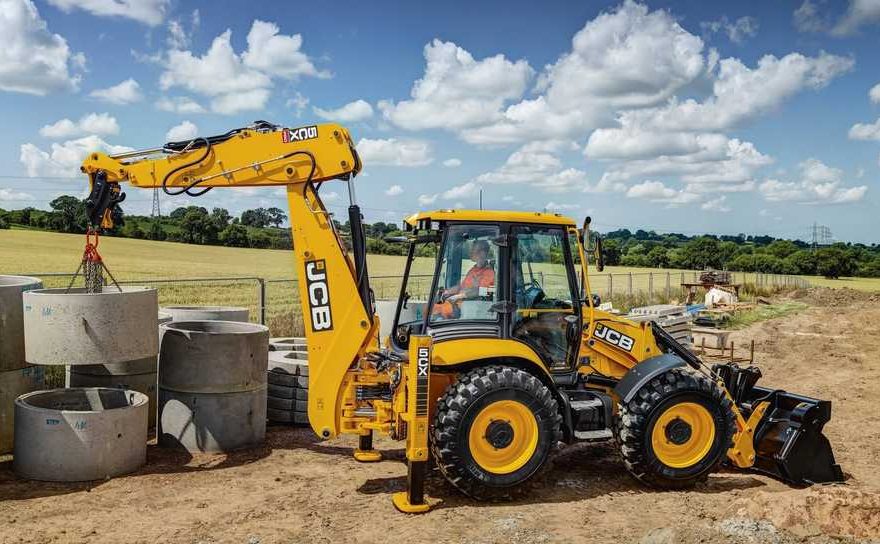
The power sideshift ram moves the backhoe carriage laterally along the rear frame rails. If the ram develops external leakage, internal bypass, damaged eye ends, bent rods, worn pins, or uneven chain movement, it may need to be removed for inspection, repair, or replacement.
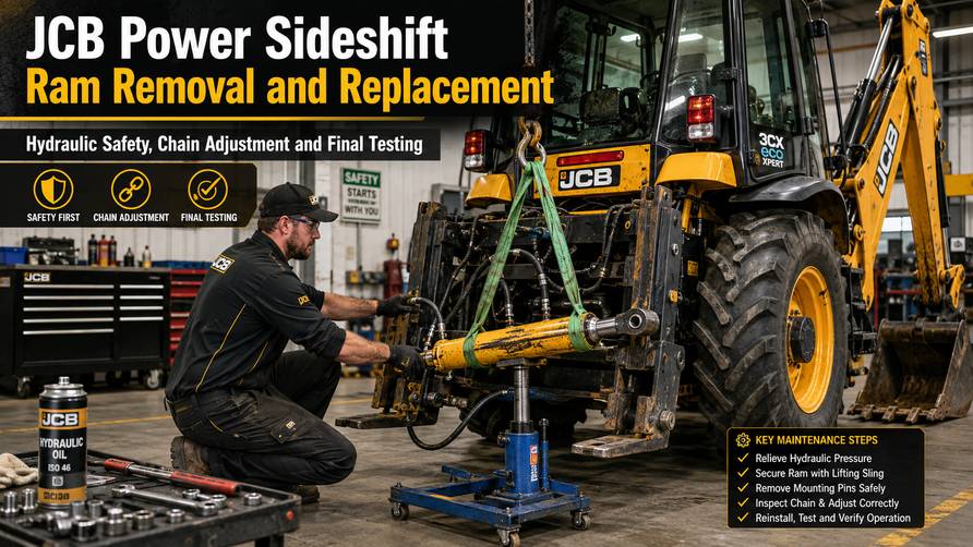
This guide explains the general removal and installation procedure for a JCB backhoe loader power sideshift ram. It also covers hydraulic safety, chain positioning, ram alignment, and final operational checks.
Important: JCB specifications can vary by machine model, serial number, carriage design, and hydraulic configuration. Confirm the correct procedure, torque values, hose routing, chain adjustment, and replacement part number in the official JCB service manual before starting work.
What Is the JCB Power Sideshift Ram?
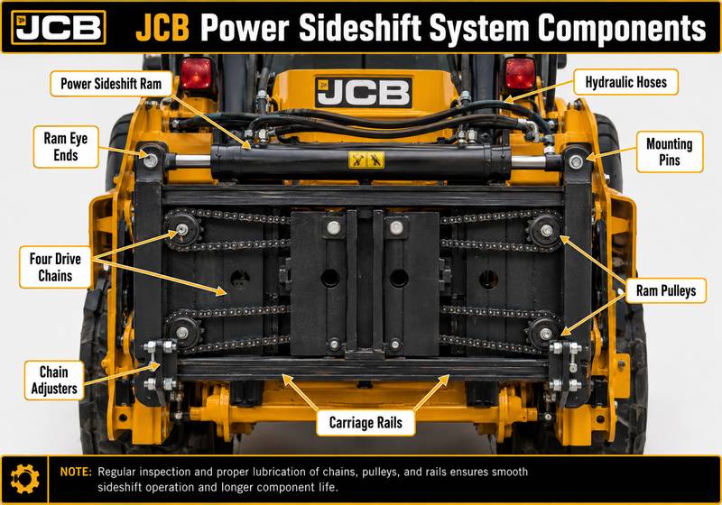
The power sideshift system allows the backhoe carriage to move sideways along the rear mounting rails. The hydraulic ram operates through a chain-and-pulley arrangement to move the carriage in either direction.
The main components normally include:
- Hydraulic sideshift ram
- Ram eye ends
- Mounting pins
- Hydraulic hoses
- Four drive chains
- Chain adjusters
- Ram pulleys
- Mounting brackets
- Carriage rails
Correct ram alignment and chain adjustment are essential. Uneven adjustment can cause poor carriage movement, accelerated chain wear, pulley damage, or excessive loading on the ram eye ends.
When Should the Power Sideshift Ram Be Removed?
Removal may be necessary when technicians find:
- Hydraulic oil leaking from the ram seals
- A bent or scored piston rod
- Internal hydraulic bypass
- Slow or uneven sideshift movement
- Damaged ram eye ends
- Worn mounting pins or bushes
- Loose or damaged chains
- Unequal ram engagement at both ends
- Abnormal movement around the pulleys
- Difficulty holding the carriage in position
Before removing the ram, confirm that the fault is not caused by low hydraulic oil, damaged hoses, incorrect chain tension, seized pulleys, valve-block problems, or restricted hydraulic flow.
Recommended Tools and Equipment
Prepare the following equipment before beginning:
- Suitable personal protective equipment
- Safety glasses and oil-resistant gloves
- Correct spanners and sockets
- Pin-removal tools
- Soft-faced hammer
- Hydraulic hose plugs and caps
- Suitable lifting or supporting equipment
- Clean drain container
- Cleaning materials
- Torque wrench
- JCB workshop manual
- JCB diagnostic equipment where electronic troubleshooting is required
For supported JCB machines, the following tools may assist with diagnosis before or after mechanical repair:
- JCB Electronic Service Tool diagnostic interface
- JCB ServiceMaster 4 diagnostic software
Diagnostic equipment can help identify hydraulic-control faults, read supported trouble codes, monitor switch status, and verify related control-system operation. It does not replace physical inspection of the ram, chains, pins, hoses, and pulleys.
Safety Precautions
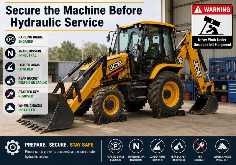
Hydraulic systems can retain pressure after the engine has been stopped. Pressurized oil can cause serious injury.
Before disconnecting any hose or removing any pin:
- Park the machine on firm, level ground.
- Apply the parking brake.
- Set the transmission to neutral.
- Lower the loader arms fully to the ground.
- Rest the backhoe bucket securely on the ground.
- Stop the engine.
- Remove the starter key.
- Operate the hydraulic controls to release residual pressure.
- Allow hot hydraulic oil and components to cool.
- Support the ram before removing the final mounting pin.
Never work under unsupported equipment. Keep hands clear of the carriage, chains, pulleys, and ram mounting points.
JCB Power Sideshift Ram Removal Procedure
Step 1: Park and Secure the Machine
Park the JCB backhoe loader on firm, level ground.
Apply the parking brake and place the transmission in neutral. Lower the loader arms until they are resting securely on the ground.
This reduces the risk of unintended machine movement while the rear hydraulic system is being serviced.
Step 2: Position the Sideshift Carriage
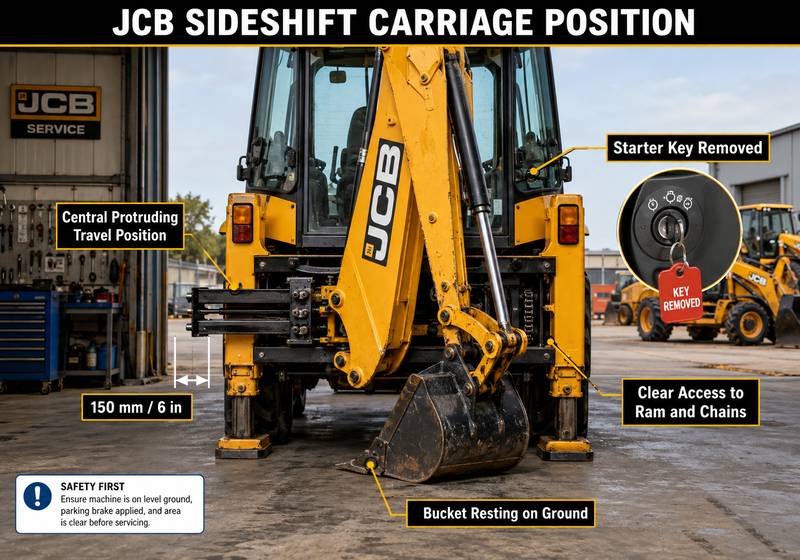
Move the carriage into the central protruding travel position.
Position it approximately:
- 150 mm
- 6 in
from the end of the rail, according to the applicable service procedure.
Rest the backhoe bucket on the ground and remove the starter key.
Correct carriage positioning provides access to the ram, chains, mounting pins, and hydraulic connections.
Step 3: Release Hydraulic Pressure
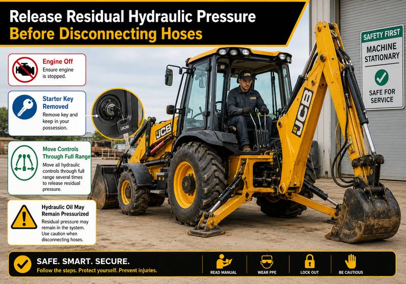
With the engine stopped, operate the relevant control levers through their full range.
This helps release trapped pressure from the hydraulic circuit.
Move the controls several times and confirm that the attachments no longer respond before opening the hydraulic system.
Slowly loosen fittings during disconnection. If pressure is still present, stop and release it safely before continuing.
Step 4: Disconnect the Hydraulic Hoses
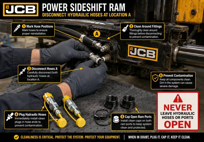
Identify the hydraulic hoses connected at location A.
Before removal:
- Clean the hose fittings and surrounding area.
- Mark each hose to ensure correct reconnection.
- Place a drain container beneath the connections.
- Disconnect the hoses carefully.
- Install clean plugs in the hoses.
- Cap the open ram ports.
Plugging and capping the system prevents contamination and reduces oil loss.
Do not allow dirt, water, metal particles, or cleaning debris to enter the hydraulic circuit.
Step 5: Disconnect the Four Chains
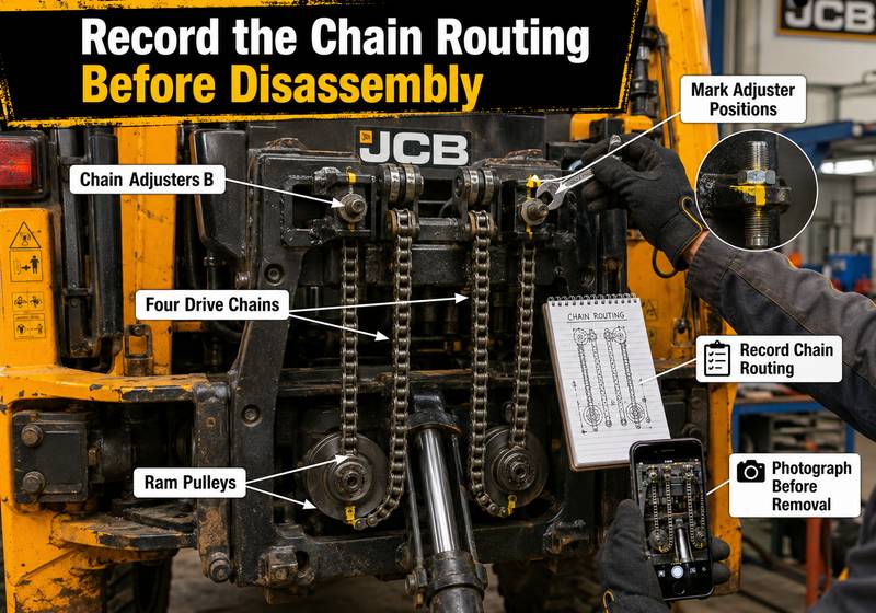
Locate the four chains and their adjusters at position B.
Release the chain tension and disconnect all four chains from the adjusters.
Carefully disengage the chains from the ram pulleys.
Before complete removal, note or photograph:
- Chain routing
- Pulley engagement
- Adjuster position
- Number of exposed threads
- Chain orientation
- Any washers, spacers, or retaining hardware
Keeping a clear record can simplify correct reassembly.
Step 6: Remove the First Ram Pin
Support the ram securely with suitable lifting equipment or a stable support.
Remove mounting pin C from one end of the ram.
Inspect the removed pin for:
- Scoring
- Pitting
- Excessive wear
- Deformation
- Corrosion
- Damaged retaining features
Do not allow the unsupported end of the ram to drop after removing the pin.
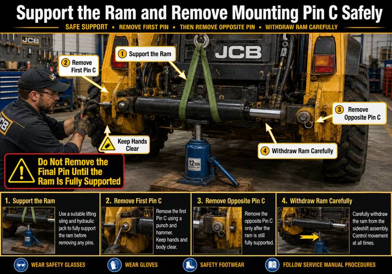
Step 7: Remove the Opposite Ram Pin
Maintain full support under the ram.
Remove mounting pin C from the opposite end.
Once both pins have been removed, withdraw the ram carefully from the machine.
Avoid damaging:
- Hydraulic fittings
- Ram eye ends
- Piston rod
- Chain pulleys
- Mounting brackets
- Nearby hoses and wiring
Place the ram on a clean, stable workbench for inspection.
Inspect the Removed Sideshift Ram
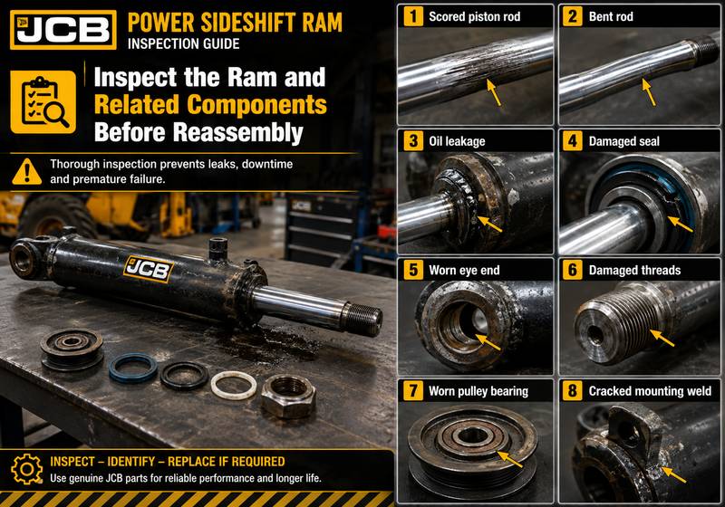
Before installing a new or repaired ram, inspect the removed assembly carefully.
Check for:
- Piston-rod scoring
- Rod bending
- Chrome damage
- Oil leakage
- Damaged seals
- Loose or worn eye ends
- Cracked welds
- Damaged threads
- Pulley wear
- Bearing play
- Contamination inside the ports
- Uneven eye-end adjustment
Also inspect the machine-side mounting brackets, pins, bushes, chains, and pulleys.
Replacing only the ram may not correct the problem if related components are already worn or misaligned.
JCB Power Sideshift Ram Replacement Procedure
Step 1: Install One End of the Ram
Position the replacement or repaired ram in the machine.
Align one ram eye with its mounting bracket and install pin C.
Secure the pin using the correct retainers specified for the machine.
Do not force the pin through misaligned components. If the pin does not enter smoothly, inspect the eye-end position, bush condition, and bracket alignment.
Step 2: Align the Opposite Ram Eye
Adjust the opposite ram eye end until it aligns with the second mounting bracket.
Install the second pin C and secure it correctly.
Both mounting pins should seat fully without excessive force.
Step 3: Equalize the Ram Eye-End Engagement
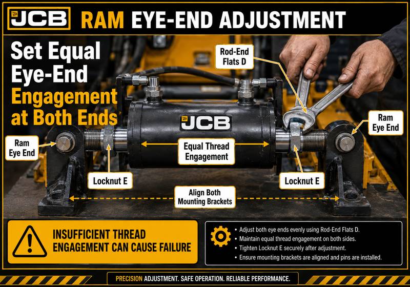
Place a spanner on the rod-end flats at position D.
Rotate the rod or eye-end adjustment until the threaded engagement is equal at both ends of the ram.
Equal engagement is important because it helps:
- Center the ram correctly
- Balance loading between the eye ends
- Maintain proper travel
- Reduce thread stress
- Support correct chain geometry
Once both ends are adjusted evenly, tighten locking nuts E to secure the eye ends.
Use the official JCB torque specification for the exact machine.
Do not leave insufficient thread engagement at either end. An incorrectly adjusted eye end may loosen, strip, or fail under load.
Step 4: Reconnect the Hydraulic Hoses
Remove the protective plugs and caps immediately before reconnecting the hoses.
Confirm that:
- The fittings are clean.
- Each hose is connected to the correct port.
- The hoses are not twisted.
- The hoses do not rub against chains or moving parts.
- The routing allows full carriage travel.
- Clamps and guards are reinstalled.
Tighten the hydraulic fittings according to the service-manual specification.
Do not overtighten fittings, as this can damage sealing surfaces or distort connectors.
Step 5: Refit the Chains
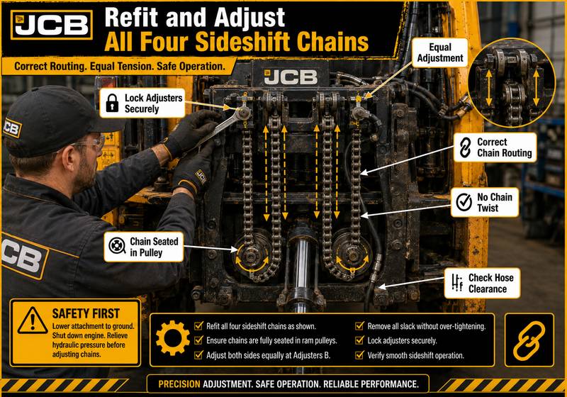
Route the four chains around the correct ram pulleys.
Confirm that each chain:
- Follows its original path
- Sits correctly in the pulley
- Is not twisted
- Is connected to the correct adjuster
- Moves freely
- Does not contact hoses or brackets
Reconnect the chains at adjuster B.
Adjust them according to the official Power Sideshift – Chain Adjustment procedure.
Why Correct Chain Adjustment Matters
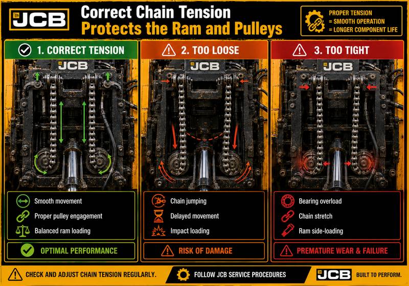
Chain adjustment affects carriage movement, ram loading, and pulley life.
Chains that are too loose may cause:
- Delayed carriage response
- Chain jumping
- Uneven movement
- Impact loading
- Poor sideshift control
Chains that are too tight may cause:
- Excessive pulley loading
- Bearing damage
- Increased friction
- Ram side-loading
- Premature chain stretch
- Accelerated eye-end wear
Both sides should be adjusted evenly according to the JCB service specification.
Bleeding and Initial Operation
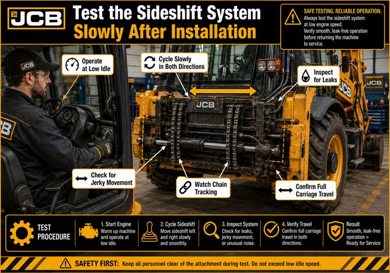
After reconnecting the hydraulic system, check the hydraulic reservoir level and top it up with the approved fluid if necessary.
Start the engine at low idle.
Operate the power sideshift system slowly in both directions. Do not immediately move the system to full travel at high speed.
Cycle the ram several times to help purge air from the circuit.
During initial operation, watch for:
- Jerky movement
- Delayed response
- Abnormal noise
- Hose movement
- Chain jumping
- Oil leakage
- Uneven carriage travel
- Contact between components
Stop the machine immediately if a serious leak or mechanical interference is found.
Final Inspection Checklist
Before returning the machine to service, confirm:
- Both ram pins are installed and secured.
- Ram eye-end engagement is equal.
- Locking nuts are tight.
- Hydraulic hoses are connected correctly.
- No fittings are leaking.
- Chains are routed correctly.
- Chain tension is adjusted to specification.
- Pulley movement is smooth.
- The carriage travels fully in both directions.
- The carriage does not bind on the rails.
- Hoses do not contact chains or moving parts.
- Hydraulic oil level is correct.
- Guards and covers are reinstalled.
- The work area is clean.
After the first operating period, inspect the ram, fittings, pins, and chain adjustment again.
Common Problems After Ram Replacement
The Carriage Moves Unevenly
Possible causes include:
- Unequal chain adjustment
- Incorrect chain routing
- Seized or worn pulley
- Unequal ram eye-end engagement
- Binding carriage rails
- Air in the hydraulic system
The Ram Leaks After Installation
Check for:
- Loose hose fittings
- Damaged seals
- Contaminated sealing surfaces
- Damaged hose ends
- Incorrect fitting installation
- A defective replacement ram
The Ram Reaches One End Before the Carriage Is Centered
Possible causes include:
- Incorrect eye-end adjustment
- Unequal threaded engagement
- Incorrect chain adjustment
- Wrong ram specification
- Incorrect mounting position
The Chains Become Loose During Operation
Inspect:
- Chain adjusters
- Locknuts
- Chain stretch
- Pulley wear
- Mounting-pin play
- Ram eye-end movement
Frequently Asked Questions
Where should the sideshift carriage be positioned before ram removal?
The commonly referenced position is approximately 150 mm (6 inches) from the end of the rail, in the central protruding travel position. Confirm the correct measurement for the exact JCB model.
Why must all four chains be disconnected?
The chains transmit ram movement through the pulley arrangement. All chains must be released so the ram can be removed without damaging the chain system or applying uncontrolled tension.
Why must the ram eye-end engagement be equal?
Equal thread engagement helps maintain ram alignment and balanced loading. Unequal adjustment may reduce available travel, overload one eye end, or cause premature thread failure.
Can the hydraulic hoses be left open during repair?
No. Open hoses and ports should be plugged or capped immediately to prevent contamination and excessive fluid loss.
Is special diagnostic equipment required to replace the ram?
The mechanical removal procedure usually does not require diagnostic software. However, the JCB Electronic Service Tool and JCB ServiceMaster may be useful when the machine has electronic control faults, stored codes, switch-input problems, or hydraulic-system performance concerns.
Should the chains be adjusted by appearance alone?
No. Chain tension and alignment should be set according to the applicable JCB service procedure. Visual estimation alone may leave the chains too tight or too loose.
Recommended JCB Diagnostic Products
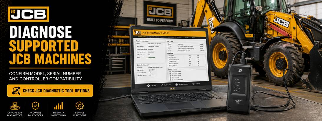
For supported JCB machinery, professional diagnostic equipment can assist with fault-code reading, live-data checks, controller identification, and post-repair verification.
JCB Electronic Service Tool Diagnostic Kit
The JCB Electronic Service Tool provides communication between a compatible computer and supported JCB machine controllers. It is useful for technicians diagnosing engine, transmission, hydraulic, and electronic control problems.
Before ordering, confirm:
- Machine model
- Serial number
- Controller type
- Diagnostic connector
- Required software version
- Required diagnostic functions
JCB ServiceMaster 4 Diagnostic Software
JCB ServiceMaster 4 provides diagnostic and service functions for supported JCB equipment. Available functions depend on the machine, controller, software version, and access level.
It may support:
- Fault-code reading and clearing
- Live-data monitoring
- Controller identification
- Service tests
- System calibration
- Troubleshooting information
- Selected programming or configuration functions
Use only software and files that are appropriate for the exact machine and controller.
Final Recommendations
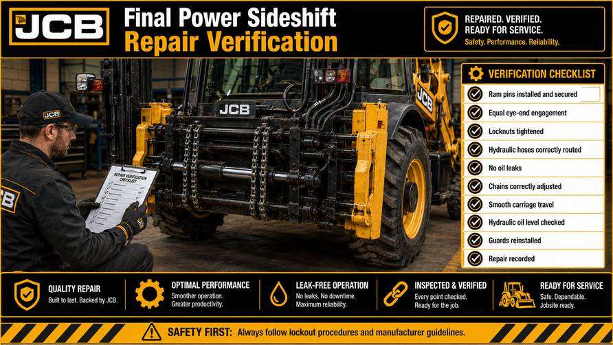
Power sideshift ram replacement is not only a hydraulic repair. Correct carriage positioning, pressure release, hose cleanliness, ram support, eye-end alignment, chain routing, and chain adjustment are all essential to a reliable repair.
The most important points are:
- Secure the machine before work.
- Release all hydraulic pressure.
- Plug every disconnected hose and port.
- Support the ram before removing pins.
- Set equal engagement at both ram eye ends.
- Route and adjust all four chains correctly.
- Test the full sideshift travel at low engine speed.
- Recheck for leaks and looseness after operation.
A correctly installed and adjusted power sideshift ram should move the carriage smoothly, hold its position, and operate without leakage, chain jumping, binding, or abnormal noise.