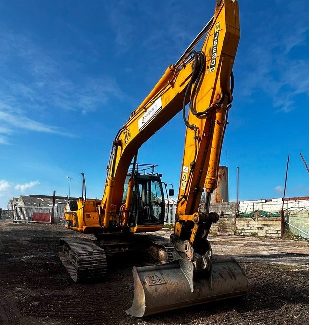
JCB Advanced Tool Select (ATS) is used on compatible excavators to control auxiliary hydraulic flow and pressure for different attachments. When ATS is incorrectly configured or calibrated, operators may experience slow attachment operation, insufficient hydraulic flow, incorrect relief pressure, or inconsistent high-flow and low-flow performance.
This guide explains the JCB 200 Series ATS setup and calibration procedure, including:
- ATS vehicle configuration
- High-flow pressure calibration
- High-flow flow calibration
- Low-flow pressure calibration
- Diagnostic checks before calibration
- Common calibration failures
- Post-calibration verification
The most important principle is:
ATS calibration adjusts the relationship between the electronic command and hydraulic output. It cannot correct a worn pump, restricted hose, faulty valve, or damaged attachment.
What Is JCB Advanced Tool Select?
Advanced Tool Select, or ATS, is JCB’s auxiliary hydraulic attachment-management system on compatible excavators.
It allows the machine to use different flow and pressure settings for hydraulic attachments such as:
- Hydraulic breakers
- Grabs
- Crushers
- Shears
- Tiltrotators
- Hydraulic compactors
- Other auxiliary hydraulic tools
Depending on machine specification, ATS may control:
- High-flow hydraulics
- Low-flow hydraulics
- One-way or two-way auxiliary operation
- Hydraulic flow
- Pressure limits
- Attachment profiles
- Joystick or pedal inputs
Do not assume every JCB 200 Series excavator has the same ATS configuration. Hydraulic options vary by machine model, serial number, market, and installed equipment.
Always confirm the exact machine configuration before changing ATS parameters.
When Should JCB ATS Be Calibrated?
ATS calibration may be required when the auxiliary hydraulic system doesn’t respond correctly, even though the basic hydraulic system is mechanically sound.
Typical symptoms include:
- Attachment operates too slowly.
- Auxiliary flow is lower than expected.
- High-flow hydraulic pressure is incorrect.
- Low-flow circuit pressure is incorrect.
- Attachment stalls too easily
- Hydraulic attachment overheats
- ATS configuration was reset
- A machine controller was replaced.
- Hydraulic control components were replaced.
- Vehicle setup parameters were changed.
However, calibration should not be the first repair step.
A similar symptom can be caused by:
- Restricted quick couplers
- Hydraulic pump wear
- Internal valve leakage
- Incorrect attachment setup
- Faulty hydraulic solenoid
- Damaged pressure sensor
- Restricted return line
- Incorrect case-drain routing
- Low engine speed
- Hydraulic oil problems
Correct these faults before attempting to compensate with ATS calibration.
Tools Required
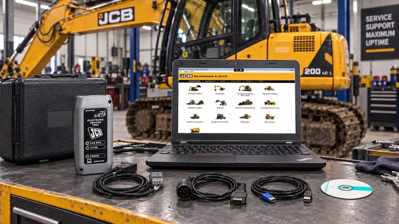
A typical ATS calibration procedure may require:
- JCB ServiceMaster diagnostic software
- Compatible JCB diagnostic interface
- Hydraulic pressure gauge or pressure sensor
- Hydraulic flow meter
- Suitable hydraulic hoses and adapters
- Machine operator display access
- Machine-specific JCB service information
- Attachment flow and pressure specifications
The original JCB procedure uses hydraulic pressure and flow measuring equipment during calibration.
Important
A diagnostic interface by itself is not enough to complete this procedure.
ServiceMaster helps verify the machine configuration, but you must still measure actual hydraulic output using suitable pressure and flow test equipment.
Hydraulic Safety Before Testing
Auxiliary hydraulic circuits can operate at extremely high pressure.
Before connecting test equipment:
- Park the excavator on stable ground.
- Lower the attachment or working equipment.
- Stop the engine when required by the service procedure.
- Relieve residual hydraulic pressure.
- Use hoses, gauges, fittings, and flow meters rated for the circuit.
- Secure test hoses away from moving and hot components.
- Check all fittings before pressurizing the system.
Never search for a hydraulic leak with your hand.
High-pressure hydraulic oil can penetrate skin and cause serious injury.
Checks to Perform Before ATS Calibration
1. Confirm the Machine Configuration
Record the machine:
- Model
- Serial number
- Hydraulic specification
- High-flow option
- Low-flow option
- ATS option
- Hydraulic merge option
- Joystick type
- Pedal type
- Auxiliary circuit configuration
Do not copy configuration settings from another excavator merely because it is the same basic model.
2. Check Hydraulic Oil Condition
Verify:
- Correct hydraulic oil level
- No obvious contamination
- No aeration or excessive foaming
- No known filter restriction
- Correct operating temperature
Hydraulic oil viscosity changes significantly with temperature.
Calibrating the system with very cold oil can result in different pressure and flow readings after the machine reaches normal operating temperature.
Follow the applicable JCB service specifications for hydraulic oil temperature during testing.
3. Scan for Active Fault Codes
Check the machine before adjusting calibration values.
Investigate active faults relating to:
- Pump control
- Auxiliary hydraulic solenoids
- Pressure sensors
- Joystick inputs
- Pedal inputs
- CAN communication
- Machine controller
- Display controller
Do not use a calibration value to hide an electrical or hydraulic fault.
4. Confirm ServiceMaster Communication
Before changing vehicle setup parameters, confirm that the diagnostic software communicates correctly with the required machine controller.
If ServiceMaster cannot communicate with the excavator, solve the communication issue first.
For interface and CAN-bus connection instructions, see:
Connection problems may involve:
- Diagnostic interface driver
- USB connection
- Machine diagnostic connector
- CAN wiring
- Power supply
- Incorrect interface selection
Avoid using an unstable USB connection or unnecessary USB hub during configuration changes.
5. Record Existing ATS Settings
Before selecting defaults or writing new configuration data, record the existing settings.
Save or photograph:
- ATS configuration
- Attachment profiles
- High-flow setting
- Low-flow setting
- Joystick type
- Pedal type
- Flow circuit type
- Current calibration values where available
This gives you a known starting point if the machine behaves differently after adjustment.
Step 1: Check JCB ATS Vehicle Setup
Open the appropriate Vehicle Setup application in JCB ServiceMaster.
The JCB 200 Series configuration screen may include settings such as:
- Low Flow
- High Flow
- Merge Fitted
- ATS Fitted
- Joystick Type
- Pedal Type
- Flow Circuit Type
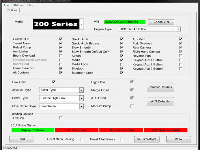
The configuration must match the hardware physically fitted to the machine.
Changing a ServiceMaster option does not add a hydraulic circuit that the machine does not physically have.
Check Joystick Type
The configuration may provide selections such as:
- Not Fitted
- Button Type
- Slider Type
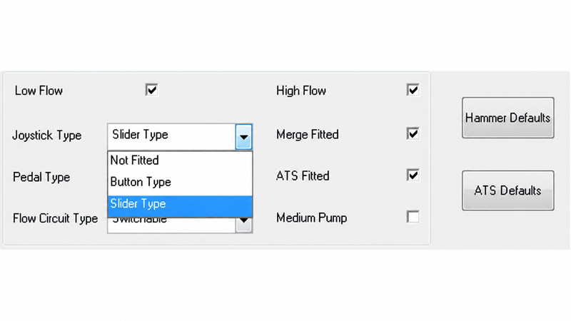
Select the actual control fitted to the excavator.
If the controller expects a slider but the machine uses another input type, the auxiliary hydraulic command may not be interpreted correctly.
Check Pedal Type
Depending on machine configuration, available options may include:
- Not Fitted
- Hydraulic Pedal
- Electric Low Flow
- Electric High Flow
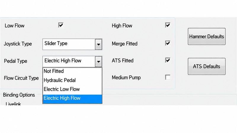
Confirm whether the installed pedal is hydraulic or electronic before changing this setting.
Check Flow Circuit Type
The ATS configuration may provide:
- 1 Way
- 2 Way
- Switchable
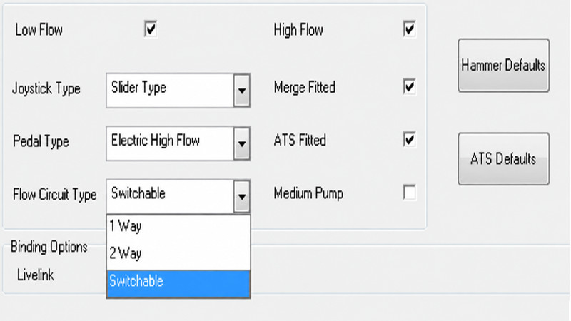
This setting matters because different attachments require different hydraulic return arrangements.
For example, a breaker normally operates differently from a bi-directional grab.
Incorrect circuit configuration can cause:
- Slow attachment operation
- Excessive return pressure
- Hydraulic heating
- Incorrect attachment direction
- Poor performance
Step 2: High-Flow Pressure Calibration
For the referenced JCB 200 Series procedure, create a temporary attachment setting using:
| Setting | Calibration Value |
| Attachment selector | Grab |
| Flow circuit | 2 Way |
| Maximum flow | 220 L/min |
| Relief pressure | 200 bar |
These are calibration test values, not recommended operating values for every attachment.
Never set an actual attachment to 220 L/min simply because the number appears in the calibration procedure.
The normal attachment setting must remain within:
- Attachment manufacturer’s limits
- Excavator hydraulic capability
- Hose and coupler capacity
Enter the ATS Calibration Menu
The referenced procedure uses the machine display.
Navigate to:
Information → Service
Then enter the appropriate service/secret menu using the specified display controls.
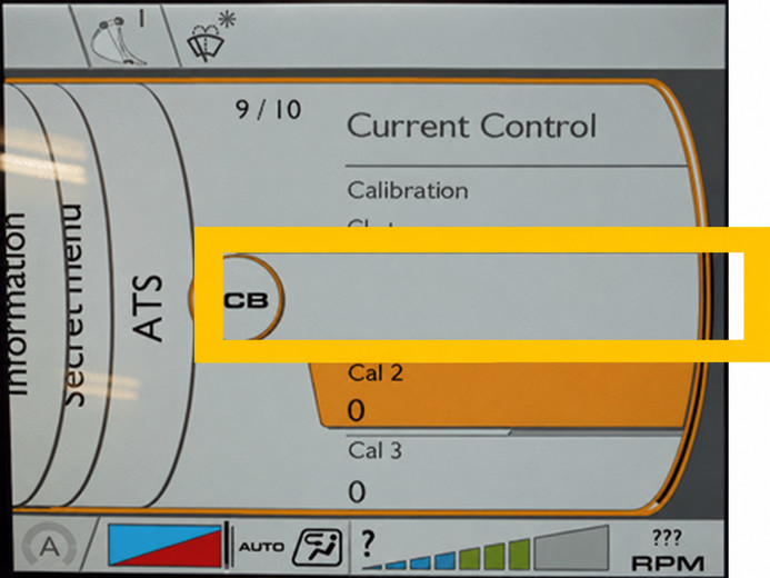
Menu access and terminology can vary with machine configuration and display/software revision.
Connect the Pressure Measuring Equipment
Install the pressure sensor or pressure gauge at the specified pump diagnostic test point.
Use the service information for the exact machine to identify the correct port.
Do not assume pressure at the attachment coupler matches pressure at the pump test port.
Pressure losses can occur through:
- Hoses
- Control valves
- Quick couplers
- Hydraulic fittings
Adjust High-Flow Pressure Calibration
Operate the auxiliary circuit under the required test conditions.
Compare:
Measured hydraulic pressure
with
Required calibration pressure
Adjust the HF Pressure Calibration value gradually until the hydraulic measurement corresponds with the required calibration specification.
Do not make large changes at once.
High-Flow Pressure Will Not Reach Specification
If increasing the calibration value does not produce the expected hydraulic pressure, stop adjusting the calibration.
Look for a hydraulic or control problem instead.
| Symptom | Possible Cause | Next Check |
| Pressure consistently low | Relief valve opening too early | Test relief pressure |
| Pressure rises slowly | Internal hydraulic leakage | Pump/valve leakage |
| Pressure unstable | Pump control or aeration issue | Pump command and oil |
| No pressure increase | Auxiliary spool not operating | Solenoid/spool |
| Calibration changes but pressure does not | Wrong circuit selected | Verify ATS configuration |
| Main hydraulics are also weak | Pump or engine problem | Main hydraulic performance |
Calibration cannot repair worn hydraulic hardware.
Step 3: High-Flow Flow Calibration
After pressure calibration, change the temporary attachment profile to:
| Setting | Calibration Value |
| Attachment selector | Grab |
| Flow circuit | 2 Way |
| Maximum flow | 150 L/min |
| Relief pressure | 200 bar |
Install the hydraulic flow meter at the test location specified by the JCB service procedure.
The referenced procedure uses the A side of the main valve block.
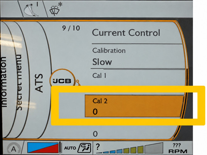
Make sure the flow meter is installed in the correct direction and rated for the expected flow and pressure.
Improper flow-meter installation can:
- Restrict hydraulic flow
- Create excessive backpressure
- Produce incorrect measurements
- Damage the test equipment.
Adjust HF Flow Calibration
Operate the auxiliary hydraulic circuit under the specified conditions.
Compare measured flow with the required calibration value.
Adjust the HF Flow Calibration value gradually until the measured flow corresponds with the required target.
Allow the hydraulic reading to stabilize before making another adjustment.
Pressure Is Correct, but Flow Is Low
This is an important diagnostic result.
If the machine reaches the correct pressure but cannot achieve the required flow, increasing the pressure calibration is unlikely to solve the problem.
Check:
- Hydraulic pump delivery
- Pump displacement control
- Engine speed under load
- Hydraulic flow-control valve
- Auxiliary spool travel
- Merge circuit operation
- Hose restriction
- Quick coupler restriction
- Oil temperature
- Flow-meter installation
A hydraulic circuit can produce normal pressure while still delivering insufficient flow.
Step 4: Low-Flow Pressure Calibration
For the referenced JCB 200 Series procedure, configure the temporary attachment profile as:
| Setting | Calibration Value |
| Attachment selector | Grab |
| Flow circuit | 2 Way |
| Maximum flow | 40 L/min |
| Relief pressure | 200 bar |
Connect the hydraulic pressure measuring equipment to the specified diagnostic port.
Enter the ATS calibration menu and adjust the low-flow pressure calibration parameter until the measured hydraulic pressure corresponds with the applicable service specification.
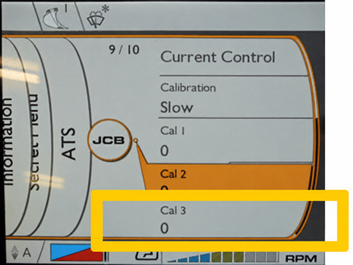
Important Note About the Original Procedure
The source procedure appears to repeat the wording “HF Pressure Calibration Value” in the low-flow pressure calibration section.
Do not automatically change the high-flow parameter again.
Verify the correct low-flow calibration parameter in the machine-specific JCB service information before making adjustments.
Changing the wrong parameter could disturb the previously completed high-flow calibration.
Does Low-Flow Flow Require Calibration?
In the referenced JCB 200 Series procedure, the low-flow circuit requires pressure calibration, while low-flow hydraulic flow does not require a separate calibration step.
This should not automatically be applied to every JCB excavator.
Always confirm the procedure for the exact:
- Model
- Serial number
- Controller
- Hydraulic configuration
Why Are 220, 150 and 40 L/min Used?
These values create specific test conditions during calibration.
Do not interpret them as universal attachment operating specifications.
The calibration sequence uses:
- 220 L/min for high-flow pressure calibration
- 150 L/min for high-flow flow calibration
- 40 L/min for low-flow pressure calibration
After testing, restore the attachment settings to values suitable for the actual tool being used.
Calibration Value vs Attachment Setting
The ATS calibration value and the normal attachment setting serve different purposes.
Calibration values correct the relationship between machine control commands and hydraulic output.
Attachment settings define how much flow and pressure a specific attachment should receive during normal operation.
For example, do not operate an attachment rated for substantially less hydraulic flow at the maximum calibration test value.
Always follow the attachment manufacturer’s hydraulic specifications.
Restore the Original Attachment Configuration
After calibration, restore the machine’s normal attachment profile.
Check:
- Attachment type
- One-way or two-way operation
- Hydraulic flow
- Pressure
- Control mode
- Joystick settings
- Pedal settings
Do not leave the temporary calibration profile active unless it matches the real attachment specification.
Post-Calibration Verification
Restart the Machine
After writing configuration changes:
- Shut the machine down normally.
- Restart it.
- Confirm the settings remain stored.
- Recheck the ATS configuration.
If configuration data disappears after every key cycle, investigate controller communication or the configuration-writing process rather than repeatedly recalibrating the machine.
Scan for Fault Codes Again
After calibration, check for new or remaining active faults.
Pay particular attention to:
- Pump control
- Hydraulic solenoids
- Pressure sensors
- Joystick inputs
- Pedal inputs
- CAN communication
Test the Actual Attachment
Restore the correct attachment profile and test the machine under controlled conditions.
Check:
- Attachment speed
- Correct direction
- Smooth operation
- Engine response
- Hydraulic noise
- Hose movement
- Oil temperature
- Leakage
Begin with conservative pressure and flow settings based on the attachment manufacturer’s specifications.
ATS Diagnostic Logic
Comparing pressure and flow together can quickly indicate where the fault is located.
| Test Result | Most Likely Diagnostic Direction |
| Pressure low + flow low | Pump supply, engine speed, pump control or major leakage |
| Pressure normal + flow low | Pump displacement, flow valve or restriction |
| Flow normal + attachment weak | Attachment or pressure limitation |
| Valve-block flow normal + attachment slow | Hose, coupler or attachment restriction |
| High flow faulty + low flow normal | High-flow circuit/configuration |
| Both circuits faulty | Common hydraulic supply or control problem |
| Hydraulic measurements normal + display values wrong | Sensor, configuration or controller issue |
This approach prevents unnecessary calibration changes.
Common ATS Calibration Mistakes
Calibrating Before Diagnosing Fault Codes
Repair active sensor, solenoid, pump-control, or communication faults first.
Testing With Cold Hydraulic Oil
Cold oil can change hydraulic resistance and measured flow.
Warm the machine according to the applicable service procedure.
Using the Wrong Pressure Test Point
Pump pressure and attachment-coupler pressure may not be identical.
Always use the specified test point.
Selecting the Wrong Hydraulic Circuit
An incorrect 1-way, 2-way, or switchable configuration can produce misleading test results.
Increasing Calibration to Compensate for a Mechanical Fault
If you can’t achieve the required pressure or flow within a reasonable calibration range, stop adjusting.
Investigate the hydraulic system.
Forgetting to Restore the Attachment Profile
The test values used during calibration may be unsuitable for normal attachment operation.
Restore the original profile after testing.
When ATS Calibration Will Not Fix the Problem
Consider this example:
Symptom: Attachment operates slowly.
Pressure: Correct.
Flow: Low.
Pressure: Correct.
Flow: Low.
The likely next diagnostic direction is:
- Pump delivery
- Pump control
- Flow-control valve
- Hydraulic restriction
Increasing relief pressure is not the correct repair.
Another example:
Pressure at the valve block: Correct
Flow at the valve block: Correct
Attachment: Still slow
Flow at the valve block: Correct
Attachment: Still slow
Check downstream components:
main valve → hose → quick coupler → attachment → return/case drain
This is where hydraulic testing becomes more important than software calibration.
Using JCB ServiceMaster During ATS Diagnosis
JCB ServiceMaster helps you check whether the machine configuration matches the installed hydraulic hardware.
For a broader explanation of ServiceMaster functions, supported machine categories, and diagnostic workflow, see:
For diagnostic-interface and CAN-bus setup, see:
Keeping these procedures separate lets technicians go straight to the information they need without repeating the full ServiceMaster setup in every repair article.
JCB ATS Calibration FAQ
What does ATS mean on a JCB excavator?
ATS means Advanced Tool Select. On compatible JCB excavators, it manages auxiliary hydraulic settings for different attachments.
Can JCB ServiceMaster calibrate ATS on its own?
No. ServiceMaster can verify or change relevant machine configuration, but the hydraulic calibration procedure also requires actual pressure and flow measurements.
Is 220 L/min the correct setting for my JCB attachment?
Not necessarily.
In this procedure, 220 L/min is a temporary high-flow pressure-calibration setting. Configure the attachment to its hydraulic requirements and the excavator’s approved operating range.
Why does the attachment remain slow even though hydraulic pressure is correct?
Normal pressure does not guarantee normal hydraulic flow.
Measure flow and investigate:
- Pump output
- Flow-control valve
- Hydraulic hoses
- Quick couplers
- Attachment restriction
Does every JCB 200 Series excavator use the same ATS calibration?
No.
ATS configuration and calibration requirements can vary by model, serial number, hydraulic option, controller, and installed equipment.
Use the service information for the exact machine.
Should ATS be recalibrated every time an attachment is changed?
Normally, no.
Once the machine’s hydraulic control system is correctly calibrated, different attachments are generally managed through their individual ATS profiles.
Recalibration corrects the machine’s hydraulic control relationship, not the normal attachment setup.
Final ATS Calibration Checklist
Before returning the excavator to service, confirm:
- Machine model and serial number were verified.
- ATS configuration matches installed hardware
- High-flow pressure was checked.
- High-flow flow was checked.
- Low-flow pressure was checked.
- Hydraulic test equipment was removed safely.
- Temporary calibration settings were removed.
- Correct attachment profile was restored.
- Attachment pressure and flow remain within specification.
- No active hydraulic-control faults remain.
- Settings remain stored after restart.
- Actual attachment operation was verified.
When ATS values are correct but hydraulic performance is still abnormal, continue diagnosing the physical hydraulic circuit rather than repeatedly changing calibration values.