When working with Scania SDP3 diagnostic software, troubleshooting can be performed by starting directly from the vehicle’s user functions. This guide explains how to navigate, check for faults, and use available tools within the user function feature.
Related Product
Navigation in User Functions
The User Functions section is organized in levels:
- Vehicle
- Group of User Functions (e.g., Gearbox Control)
- User Function (e.g., Opticruise System)
- Application
- Scenario (different ways a use case can be executed)
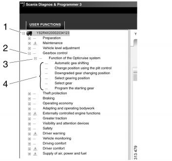
Example: Within the Gearbox Control group, one user function is the Opticruise System. This may include applications such as:
- Activating automatic gear changes
- Selecting gears manually
- Setting the starting gear
The available tabs and functions depend on where you are in the navigation tree.
Information Available at Different Levels
The type of data you can access varies by navigation level:
| Level | Fault Codes | Description | Check | Function Diagram | Adjustment |
|---|---|---|---|---|---|
| Vehicle | X | ||||
| Group of User Functions | X | X | |||
| User Function | X | X | X | X | X |
| Application | X | X | |||
| Scenario (Use Case Options) | X | X |
Key Features
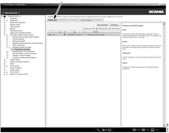
1. Fault Codes
Displays registered fault codes linked to a specific user function. These are presented in the same way as fault codes under the Electrical System.
2. Description
Provides a short explanation of what the selected user function does.
3. Check
Enables functional checks of certain user functions. Unlike checks in the electrical system, these may involve multiple interconnected control units.
Steps:
- Highlight the desired user function.
- Start the check wizard by pressing the corresponding button.
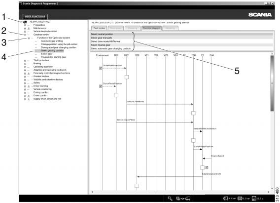
4. Function Diagram (Message Sequence Chart)
Shows a graphical overview of how a user function operates:
- Blue broken arrow (1): Influence from external actions (e.g., driver turning the starter key).
- Blue solid arrow (2): Conventional electrical signals (e.g., switch closes circuit to supply +24V).
- Black arrow (3): CAN messages exchanged between control units.
- Right-click component (4): Directs you to detailed circuit checks in the electrical system view.
This diagram helps visualize the flow of signals and interactions between control units and components in the selected user function.
Practical Use
By navigating to a user function, technicians can:
- Identify and interpret fault codes
- Understand the role of the function in the vehicle
- Run targeted checks on involved systems
- Use message sequence charts for a clear overview of communication and signal paths
This structured approach within Scania SDP3 makes it easier to diagnose and resolve issues across multiple systems, ensuring more accurate troubleshooting.

Note: Compatible with Scania SDP3 2.66.x diagnostic software versions for trucks, marine, and industrial applications.