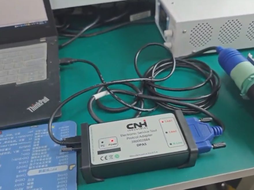
Excessive swing overrun can be a dangerous problem in hydraulic excavators. When the operator returns the swing control lever to neutral, the upper structure should decelerate smoothly and stop within the manufacturer-specified limits. If the excavator continues rotating farther than expected, the problem may involve the swing hydraulic circuit, control valve, swing motor, or brake system.
In this guide, we examine a CASE excavator swing overrun case in which technicians found a rubber particle blocking an oil return orifice in the swing motor brake circuit.
We will explain the possible causes, diagnostic procedures, inspection results, repair process, and how CNH diagnostic software can assist with electronically controlled systems.
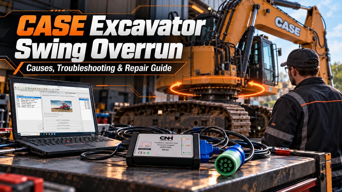
1. What Is Swing Overrun in a CASE Excavator?
Swing overrun occurs when an excavator’s upper structure continues rotating excessively after the operator releases the swing joystick.
A small amount of continued movement is normal because the rotating upper structure has significant inertia. However, excessive or inconsistent movement can indicate a braking or hydraulic control problem.
Common Symptoms
- The upper structure rotates too far after the swing lever returns to neutral.
- Swing stopping distance is longer than normal.
- The excavator feels difficult to position accurately.
- Swing stopping behaviour becomes inconsistent.
- The swing brake may engage later than expected.
- The machine may have difficulty holding its position after stopping.
Excessive swing overrun increases the risk of collisions, equipment damage, and unsafe operation near workers or structures.
Important: Excessive swing stopping distance and delayed swing parking brake engagement are related symptoms, but they are not necessarily the same fault.
2. How Does the Excavator Swing Braking System Work?
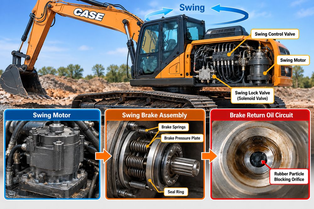
Understanding the braking system helps technicians identify the correct component before disassembly.
Depending on the excavator model, the swing system may include:
- Hydraulic swing motor
- Main swing control valve
- Swing crossover relief valves
- Swing brake solenoid or lock valve
- Brake piston and springs
- Hydraulic pressure and return passages
- Electronic control module
Hydraulic Swing Braking
On many excavators, the swing control circuit creates hydraulic resistance that slows the upper structure when the operator returns the joystick to neutral.
The main control valve and swing relief circuits play important roles in controlling deceleration.
Problems such as internal leakage, sticking valve spools, or malfunctioning crossover relief valves may increase swing stopping distance.
Swing Parking Brake
Many excavators also use a spring-applied, hydraulically released swing parking brake.
When sufficient hydraulic release pressure is applied, the brake piston moves against the spring force, allowing rotation.
When the release pressure is removed, the springs engage the brake to hold the upper structure in position.
The return oil circuit controls how the brake chamber discharges hydraulic pressure.
Technical note: The swing parking brake typically holds the stopped upper structure rather than serving as the primary dynamic stopping brake. Its engagement timing and relationship to swing deceleration depend on the machine’s specific hydraulic design.
This distinction is essential when troubleshooting excessive rotation.
3. Common Causes of Excessive Swing Overrun
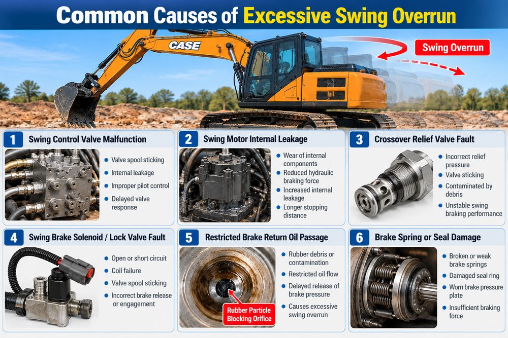
Several problems may cause abnormal swing behavior on a CASE excavator.
| Possible cause | Typical problem | Recommended inspection |
|---|---|---|
| Swing control valve malfunction | Valve spool sticks or fails to return correctly | Inspect spool movement and pilot control |
| Swing motor internal leakage | Reduced hydraulic braking performance | Perform OEM leakage tests |
| Crossover relief valve fault | Incorrect swing braking pressure | Test relief valve operation |
| Swing brake solenoid fault | Incorrect brake release or engagement command | Check wiring, coil, and valve |
| Restricted brake return orifice | Delayed discharge of brake release pressure | Inspect return oil passages |
| Brake spring or piston damage | Weak or irregular holding brake engagement | Inspect brake assembly |
| Hydraulic oil contamination | Restricted passages or sticking components | Inspect oil, filter, seals, and hoses |
The correct diagnosis should separate dynamic swing-stopping problems from parking-brake engagement or holding problems.
4. CASE Excavator Swing Overrun: Real Troubleshooting Case
Reported Problem
During excavator operation, the upper structure continued rotating excessively after the swing control lever returned to neutral.
The operator noticed abnormal swing-stopping behaviour.
The technicians investigated the swing lock valve, brake release pressure, and internal swing motor brake components.
The original repair record does not identify the exact CASE excavator model or serial number. Therefore, treat the measurements and observations below as case-specific rather than universal CASE specifications.
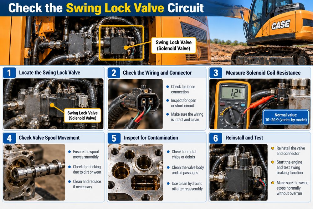
Step 1: Inspect the Swing Lock Valve Circuit
The first diagnostic step was to inspect the swing lock valve electrical circuit.
Technicians checked:
- Wiring connections to the swing lock valve.
- Electrical connectors for looseness or corrosion.
- The circuit for open or short conditions.
- Solenoid coil condition.
- Mechanical movement of the solenoid valve spool.
On an electronically controlled swing brake system, a damaged wire or sticking solenoid can interfere with normal brake release or engagement.
Electrical resistance, voltage, and solenoid command checks should follow the specific machine’s service manual.
Diagnostic approach: Confirm that the electrical command and hydraulic valve response are correct before replacing the solenoid or control module.
Step 2: Measure Swing Brake Release Pressure
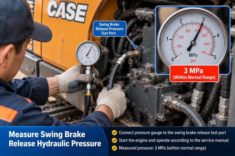
Next, technicians measured the hydraulic pressure in the swing brake release circuit.
Recorded measurement: 3 MPa
According to the original repair record, this pressure was within the acceptable range for the machine being tested.
This result reduced the likelihood that inadequate brake-release supply pressure was the immediate fault.
However, a normal release-pressure reading does not prove that pressure decays at the correct rate when the swing control returns to neutral.
A restricted return passage may allow normal pressure during brake release while delaying pressure discharge afterwards.
Important: The 3 MPa value is a measurement from this particular case. Always consult the correct CASE service documentation for the specified pressure, measurement port, operating conditions, and test procedure.
Step 3: Remove and Inspect the Swing Motor
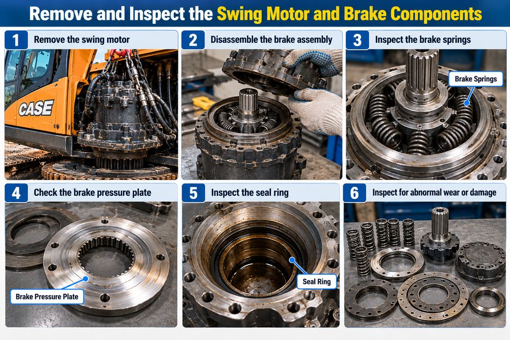
Because the initial checks did not identify the problem, the technicians inspected the swing motor brake assembly.
Before removing hydraulic components:
- Park the machine on stable ground.
- Lower the attachment to a safe position.
- Shut down and secure the machine.
- Follow the manufacturer’s hydraulic pressure-relief procedure.
- Prevent unintended upper-structure movement.
- Use appropriate lifting equipment for heavy components.
Hydraulic oil can remain pressurised after engine shutdown. Never loosen hydraulic connections before safely depressurising the system.
During the swing motor inspection, technicians examined the brake springs, brake pressure plate, sealing components, and internal return passages.
They specifically checked whether:
- The brake springs were broken or damaged.
- The springs showed abnormal wear or loss of tension.
- The brake pressure plate sealing ring was damaged.
- Hydraulic passages were obstructed.
Step 4: Inspect the Brake Return Oil Circuit
During inspection of the swing motor brake return circuit, technicians discovered a small rubber particle near an oil return orifice.
The orifice was not completely blocked. However, the rubber debris restricted the flow of hydraulic oil.
This was the key finding in the repair case.
The restriction could delay the release of hydraulic pressure from the brake chamber, interfering with the intended brake engagement timing.
The reported fault was resolved after cleaning the contaminated components.
Why Can a Partially Blocked Orifice Matter?
Small hydraulic orifices control oil flow and pressure changes.
When the return passage becomes restricted:
- The swing brake release chamber may discharge oil more slowly.
- Hydraulic release pressure may remain for longer than intended.
- Spring-applied brake engagement may be delayed.
- The upper structure may remain without its intended holding-brake engagement for longer.
A small rubber fragment may therefore affect a brake timing circuit even if oil can still pass through the opening.
However, delayed parking brake engagement alone does not establish the cause of excessive dynamic swing deceleration distance on every excavator. The swing control valve, motor leakage, and relief circuits must also be considered.
5. Repair Procedure: Cleaning the Restricted Oil Passage
Once the rubber particle was identified, the technicians cleaned the affected swing motor brake components.
Particular attention was given to:
- Brake return oil orifice
- Small hydraulic passages
- Brake piston and sealing surfaces
- Internal oil channels
- Components exposed to contamination
Recommended Repair Practices
1. Remove contamination carefully
Use manufacturer-approved cleaning methods to remove rubber fragments and other debris.
Avoid pushing contamination deeper into hydraulic passages.
2. Inspect seals and rubber components
A rubber fragment may originate from a deteriorated O-ring, hose lining, or another sealing component.
Inspect related parts to identify the contamination source and prevent recurrence.
3. Check internal components
Inspect the brake springs, piston, sealing ring, and friction components against manufacturer specifications.
Replace damaged parts when necessary.
4. Reassemble according to the service manual
Use the correct seal installation methods, tightening specifications, and required cleanliness procedures.
5. Restore and check the hydraulic system
After reassembly, refill or restore hydraulic fluid as required, follow the prescribed air-removal procedure, and check for leaks.
Do not enlarge the original orifice or modify the brake circuit to change stopping characteristics.
6. Test Results: Swing Overrun Problem Resolved
After cleaning the swing motor brake components and restricted return passages, technicians reassembled the system and tested the excavator.
The reported results were:
| Inspection item | Finding |
|---|---|
| Brake release pressure | 3 MPa, acceptable in the recorded case |
| Brake springs | No abnormal damage reported |
| Brake pressure plate sealing ring | No damage reported |
| Brake return oil passage | Rubber particle restricting flow |
| Repair action | Cleaned swing motor components and narrow passages |
| Final swing operation | Overrun returned to the specified limits |
| Repair status | Fault resolved |
The successful repair demonstrates the importance of inspecting small hydraulic passages rather than immediately replacing expensive swing motor or control assemblies.
It also illustrates why pressure measurement alone may not reveal a hydraulic timing restriction.
How to Verify the Repair
After completing the repair, technicians should perform the manufacturer’s specified swing braking and holding tests.
With the machine in a controlled, clear test area, verify:
- Smooth swing acceleration and deceleration.
- Normal stopping distance in both directions.
- Correct swing brake holding function.
- No unusual noises or vibration.
- No hydraulic leaks.
- No abnormal electrical or hydraulic diagnostic faults.
Use the exact operating conditions and permissible stopping angle specified for the machine model.
7. Using CNH EST 9.15 for CASE Excavator Diagnostics
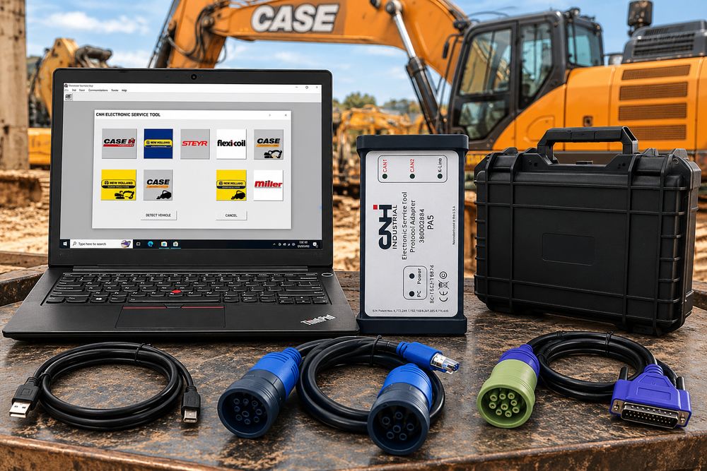
Mechanical and hydraulic inspection remains essential when troubleshooting excessive swing overrun.
However, when the CASE excavator has supported electronically controlled swing or hydraulic systems, CNH EST diagnostic software may help technicians investigate related electrical and controller faults.
Depending on model, controller, and access level, supported functions may include:
- Reading active and stored diagnostic trouble codes.
- Monitoring available sensor and controller parameters.
- Checking electrical control system status.
- Accessing applicable diagnostic procedures.
- Reviewing available wiring and hydraulic information.
- Performing supported tests and service operations.
For more information, read our detailed guide:
CNH EST Diagnostic Tool Guide: Case IH & New Holland Diagnostics, Programming and Setup
Recommended CASE & New Holland Diagnostic Tools
Option 1: CNH DPA5 Diagnostic Kit with CNH EST 9.15
For workshops that need a diagnostic communication interface and software package, the CNH DPA5 kit is a practical option for supported CASE and New Holland machinery.
View CNH EST 9.15 DPA5 Diagnostic Kit
Option 2: CNH EST 9.15 Engineering-Level Diagnostic Software
For technicians who already have a compatible diagnostic adapter and laptop, a software-only package may be suitable.
View CNH EST 9.15 Engineering Diagnostic Software
Note: Before purchasing, verify the excavator model, year, serial number, electronic system, interface compatibility, and required software coverage. Diagnostic software can support electrical troubleshooting, but it cannot directly remove physical contamination from a hydraulic passage.
8. How to Prevent Future Swing Hydraulic Problems
Regular maintenance can help reduce the likelihood of contamination-related swing system problems.
Maintain Hydraulic Oil Cleanliness
Use hydraulic fluid that meets the manufacturer’s requirements.
Contaminated or degraded oil can contribute to valve sticking, component wear, and restricted passages.
Replace Hydraulic Filters on Schedule
Follow the manufacturer’s replacement intervals and inspect filters when hydraulic contamination is suspected.
Inspect Seals and Hoses
Deteriorated rubber components may release small particles into the hydraulic circuit.
Replace damaged seals, hoses, and related components as required.
Monitor Swing Operation
Watch for changes in stopping distance, uneven deceleration, unusual noises, or abnormal swing-holding behaviour.
Early diagnosis can help prevent more serious hydraulic component damage.
Follow Machine-Specific Service Procedures
Do not assume CASE excavators of different generations use the same swing hydraulic or braking systems.
Always use the service procedures applicable to the model and serial number.
9. Frequently Asked Questions
Why does my CASE excavator keep swinging after I release the joystick?
Some movement after returning the joystick to neutral is normal due to inertia. Excessive movement may result from swing control valve problems, motor leakage, crossover relief valve faults, or other hydraulic braking issues. Also check for brake engagement problems when symptoms indicate delayed holding-brake operation.
Can a blocked hydraulic orifice cause swing brake problems?
Yes. A restricted return passage can delay brake-release pressure discharge and affect the engagement timing of a spring-applied brake. The actual effect on swing stopping distance depends on the excavator’s design.
Is 3 MPa the correct swing brake pressure for every CASE excavator?
No. We recorded the 3 MPa reading in the troubleshooting case described above. Pressure specifications vary by excavator model and system. Always use the correct service manual.
Does the swing parking brake stop the excavator’s upper structure?
On many excavators, hydraulic braking controls normal swing deceleration, while the parking brake holds the upper structure once stopped. Check the machine-specific design before diagnosing the braking system.
Can CNH EST 9.15 diagnose swing problems on a CASE excavator?
CNH EST 9.15 can help diagnose supported electronic controls by reading fault codes, live data, and related diagnostic information. It cannot directly determine whether a small hydraulic orifice contains debris without physical inspection.
Should I replace the swing motor if the excavator has excessive swing overrun?
Not necessarily. Before considering swing motor replacement, check the hydraulic control system, relief valves, internal leakage, brake circuit, and oil passages. In this case, cleaning the restricted return orifice resolved the reported problem.
Conclusion
Excessive swing overrun in a CASE excavator requires a systematic approach to diagnosing the hydraulic and brake systems.
In this repair case, technicians checked the swing lock valve circuit, measured brake release pressure at 3 MPa, and inspected the swing motor brake assembly. They eventually found a rubber particle blocking an oil-return orifice.
After cleaning the contaminated passages and reassembling the components, the machine’s swing overrun returned to the specified limits.
The key lesson is that small hydraulic restrictions can cause significant control problems, even when a pressure reading appears normal.
For workshops maintaining CASE and New Holland equipment, combining careful mechanical inspection, accurate hydraulic testing, manufacturer service information, and appropriate diagnostic tools such as CNH EST 9.15 provides a more effective troubleshooting workflow.
OBD2TOOL Technical Support Team — Heavy Equipment Diagnostics & Repair Guides
Disclaimer: This article is based on a reported field repair case and general hydraulic troubleshooting principles. Machine-specific service documentation takes precedence over the procedures described here.