
Quick Answer
An OBDII scanner is worth buying when its diagnostic capability matches the vehicle and the work you intend to perform. A basic scanner can read standardized emissions-related Diagnostic Trouble Codes (DTCs), while professional diagnostic tools may add manufacturer-specific modules, live data, active tests, coding, calibration, or programming. These functions aren’t interchangeable and aren’t universally supported.
For a professional workshop, the most reliable buying sequence is:
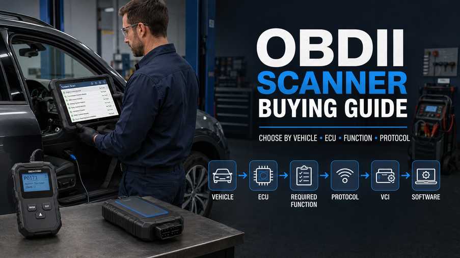
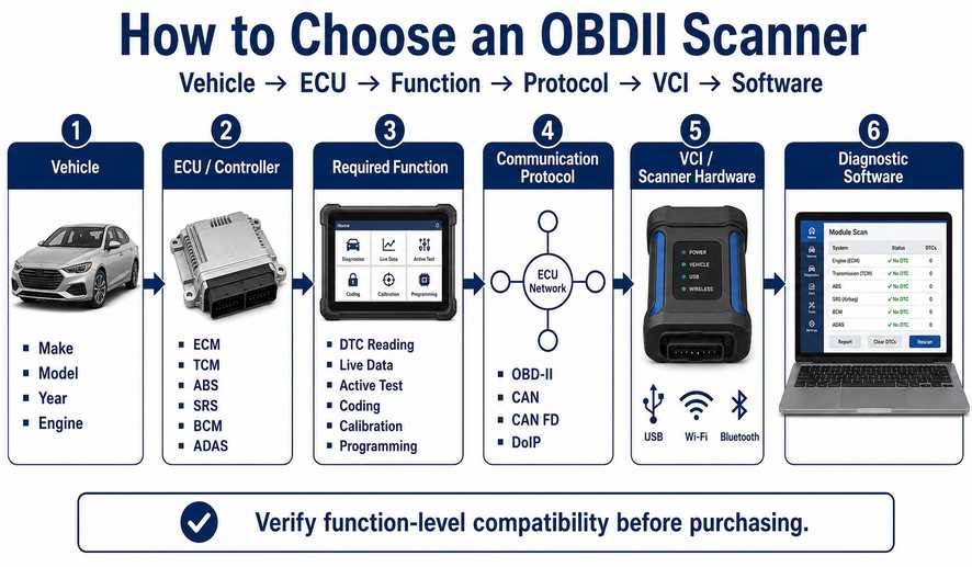
Vehicle → ECU → Required Function → Communication Protocol → Interface → Software
Do not choose a scanner simply because its product page says “OBD2,” “full system,” or “all cars.”
Key Takeaways
- OBD-II is a diagnostic standard, not a guarantee of full vehicle access.
- Reading an engine fault code does not mean the scanner can diagnose ABS, SRS, BCM or ADAS systems.
- A DTC identifies a detected condition; it does not automatically identify the failed part.
- Live data, active tests, coding, programming and calibration are different functions.
- Passenger-car OBD-II scanners are not automatically suitable for heavy-duty trucks or construction equipment.
- Newer vehicles may require CAN FD, DoIP, or manufacturer security authorization.
- Before buying, verify make, model, year, engine, ECU, connector, protocol, and required function.
What Does an OBDII Scanner Actually Do?
An On-Board Diagnostics II (OBD-II) scanner communicates with a vehicle’s diagnostic system through the diagnostic connector. Standard OBD-II was designed primarily for emissions-related monitoring and diagnostic information. More capable aftermarket tools add manufacturer-specific software that can communicate with additional control modules and perform functions beyond generic OBD-II.
SAE J1962 defines the standardized diagnostic connector used for OBD applications, including connector design and electrical requirements. This standardization helps compatible test equipment connect to compliant vehicles, but it does not require every aftermarket scanner to provide identical manufacturer-specific functions.
In the United States, OBD-II became broadly required on light-duty vehicles in the 1990s. CARB states that 1996-and-newer gasoline and alternative-fuel passenger cars and trucks must have OBD-II, while diesel passenger cars and trucks followed from the 1997 model year under California requirements.
The practical workshop lesson is simple:
A standardized connector does not equal standardized access to every ECU.
Where Does Generic OBD-II End?
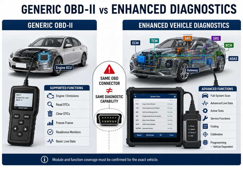
Generic OBD-II mainly gives technicians access to standardized emissions-related diagnostic information. Access to ABS, airbag, body, immobilizer, ADAS, transmission adaptations, or manufacturer-specific service routines generally requires enhanced diagnostic support for that particular vehicle.
A low-cost code reader may provide:
- Stored DTCs
- Pending DTCs
- Check Engine Light status
- Freeze-frame information
- Selected live Parameter IDs (PIDs)
- Emissions readiness information
- Code clearing
A more advanced diagnostic platform may additionally provide:
- ABS diagnostics
- Supplemental Restraint System (SRS) diagnostics
- Transmission diagnostics
- Body Control Module (BCM) access
- Electronic Parking Brake service
- Steering-angle calibration
- Injector coding
- DPF service functions
- Bidirectional active tests
- ECU configuration
- Programming functions
Confirm these functions are available for your exact vehicle.
A scanner that supports ABS on one Volkswagen does not mean it supports the same function on every Volkswagen, Audi, Mercedes-Benz, Ford, or Toyota.
Is an OBDII Scanner Suitable for Trucks and Heavy Equipment?
A conventional passenger-car OBDII scanner should not be assumed to support commercial trucks, agricultural machines, or construction equipment. Heavy-duty vehicles may use HD-OBD, SAE J1939, manufacturer-specific communication systems, or dedicated service software that requires a different interface.
CARB notes that heavy-duty vehicles above 14,000 lb began using heavy-duty OBD requirements from later model years, rather than following the same implementation path as light-duty passenger vehicles.
For a technician working on equipment such as:
- Cummins-powered trucks
- Scania vehicles
- Caterpillar machinery
- John Deere equipment
- CASE/New Holland agricultural machinery
- Doosan/DEVELON excavators
- Volvo construction equipment
The correct diagnostic solution may require an OEM-specific or heavy-duty interface rather than a conventional passenger-car OBD2 scanner.
Before selecting a tool for heavy-duty work, confirm:
Machine/Truck + Model + Year + Engine + Controller + Connector + Protocol + Software + Required Function
Six Scanner Functions You Should Not Confuse
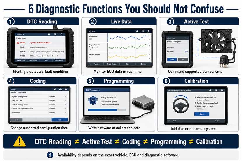
Choosing the correct scanner requires understanding exactly what each advertised function means. Reading DTCs, performing active tests, coding, programming, and calibration operate at very different levels of vehicle control, and a tool supporting one function does not automatically support the others.
1. Read and Clear DTCs
A Diagnostic Trouble Code records a condition a control module detects.
For example, a code relating to an oxygen sensor circuit does not automatically prove that the oxygen sensor itself has failed.
Possible causes may include:
- Sensor failure
- Wiring damage
- Connector corrosion
- Power or ground failure
- Exhaust leak
- ECU input problem
The DTC is the starting point of diagnosis, not the parts-ordering instruction.
2. Live Data
Live data shows values reported by sensors, calculated parameters, or ECU states.
Examples include:
- Engine speed
- Coolant temperature
- Fuel trim
- Accelerator position
- Airflow
- Oxygen-sensor information
- System voltage
The value becomes useful only when compared with the vehicle operating condition and manufacturer specifications.
3. Active Test / Bidirectional Control
An active test commands an ECU to operate a component or change a state.
Examples can include commanding:
- Cooling fan
- Fuel pump
- Relay
- Solenoid
- Door lock
- EGR actuator
Availability depends on the vehicle, ECU, and diagnostic software.
Use active tests carefully because some commanded devices can move, pressurize, heat, or activate unexpectedly.
4. Coding
Coding changes supported configuration data or enables the ECU to recognize a particular vehicle configuration.
Coding is not the same as installing new ECU firmware.
Confirm exact availability based on the specific vehicle, controller version, and diagnostic software.
5. ECU Programming
Programming usually means writing software, firmware, or calibration data to an ECU.
This is a higher-risk operation than reading fault codes.
Programming can require:
- Stable battery support
- Correct communication interface
- Correct software package
- Internet access
- OEM account or subscription
- Security authorization
- Correct calibration file
Never assume a scanner can perform OEM ECU programming simply because its description includes “ECU coding.”
6. Calibration / Relearn
Calibration teaches or initializes a system after repair, component replacement, or adjustment.
Examples may include:
- Steering Angle Sensor calibration
- Transmission adaptation
- Throttle relearn
- Ride-height calibration
- ADAS calibration
Required procedures vary considerably by vehicle.
What Should You Prepare Before Connecting a Diagnostic Scanner?
A reliable diagnostic session starts with the vehicle and communication path, not with the fault-code screen. Confirm stable vehicle power, an intact diagnostic connector, the correct scanner software, and the exact vehicle before interpreting data or commanding modules.
Prepare:
- Compatible diagnostic scanner
- Correct vehicle cable or VCI
- Charged diagnostic tablet/laptop
- Appropriate vehicle battery support when required
- Vehicle wiring information when troubleshooting communication
- Correct diagnostic software
- Vehicle VIN
- Make, model, year, and engine information.
For professional work, also identify the ECU or controller involved.
Check Vehicle Power First
Low system voltage can cause modules to reset, disappear from a vehicle scan, or generate misleading communication faults.
Do not use one fixed battery-voltage threshold for every programming procedure.
For ECU programming, follow the manufacturer’s specified battery-support requirements.
Inspect the Diagnostic Connector
Look for:
- Damaged terminals
- Bent contacts
- Loose connector body
- Corrosion
- Missing power
- Poor ground
- Previous aftermarket wiring modifications
If power or ground at the diagnostic connector is abnormal, repair the vehicle-side problem before blaming the scanner.
How Should You Choose an OBDII Scanner?
Choose the scanner by required function rather than by price or the number of advertised features. Start with the exact vehicle population you service, identify the controllers you need to access, determine the operations you need to perform, and then verify that the scanner hardware and current software support those combinations.
Use this sequence.
Step 1 — Define the Vehicle
Record:
- Manufacturer
- Model
- Model year
- Engine
- Region
- VIN when available
Step 2 — Define the Controller
Do you need access only to the Engine Control Module (ECM), or also:
- Transmission Control Module
- ABS
- SRS
- BCM
- Immobilizer
- ADAS
- HVAC
- Gateway
Step 3 — Define the Function
Choose what you actually need:
- DTC reading
- Live data
- Active tests
- Service resets
- Coding
- Calibration
- Programming
Step 4 — Confirm the Communication Technology
Depending on the vehicle, relevant technologies may include:
- Conventional OBD-II protocols
- Controller Area Network (CAN)
- CAN FD
- Diagnostics over Internet Protocol (DoIP)
- Manufacturer-specific communication
Verify protocol support for the target vehicle.
Step 5 — Confirm Software Coverage
Hardware alone is not enough.
A capable Vehicle Communication Interface (VCI) still depends on software coverage for the target ECU and function.
Step 6 — Check Update and Access Requirements
Determine whether the function requires:
- Subscription
- Software update
- OEM login
- Security Gateway access
- Internet connection
- Separate programming software
For professional workshop use, you can compare different OBD2 diagnostic tools by vehicle coverage, ECU access, active tests, coding, programming capability and communication protocol.
Basic Code Reader vs Full-System Scanner vs Professional Platform
The correct scanner category depends on what happens after you read the first DTC. A basic reader is adequate for standardized engine/emissions checks, while professional diagnostics often require multi-module access, bidirectional testing, protocol support, and manufacturer-specific software.
| Capability | Basic OBD-II Reader | Full-System Scanner | Professional Platform |
| Generic engine DTCs | Usually | Usually | Usually |
| Freeze frame | Often | Yes | Yes |
| Live data | Basic | Expanded | Expanded |
| ABS/SRS | Usually no | Common | Common |
| Multiple ECUs | Limited | Yes | Yes |
| Active tests | Usually no | Model-dependent | Model-dependent |
| Service functions | Limited | Common | Common |
| ECU coding | No/limited | Vehicle-dependent | Vehicle-dependent |
| ECU programming | Usually no | Limited/model-dependent | Platform-dependent |
| CAN FD / DoIP | Usually no | Model-dependent | Interface-dependent |
| Heavy-duty support | Usually no | Usually separate | Platform-dependent |
Never treat this table as a vehicle compatibility list. Confirm exact functions for your specific vehicle and software version.
Why Will an OBDII Scanner Not Connect?
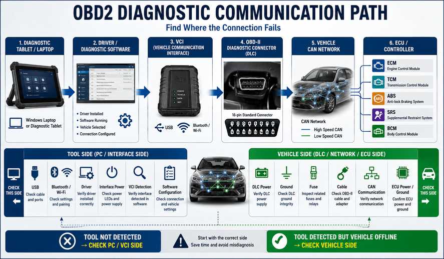
First, divide a no-communication problem into two categories: the computer or tablet cannot detect the diagnostic interface, or the interface is detected but cannot communicate with the vehicle. These failures occur on opposite sides of the communication chain and should not be diagnosed with the same procedure.
The communication path is:
Tablet/Laptop → Driver/Software → VCI → Diagnostic Connector → Vehicle Network → ECU
Reason Priority Table
| Priority | Possible cause | First check |
| 1 | Vehicle/DLC has no power | Check vehicle battery, fuse and connector supply |
| 2 | Ignition state incorrect | Follow diagnostic software instructions |
| 3 | Damaged/incorrect cable | Inspect and substitute known-good cable |
| 4 | Scanner/interface not detected | USB/Bluetooth/Wi-Fi/driver check |
| 5 | Incorrect vehicle selection | Verify VIN/model/year/engine |
| 6 | Network fault | Check CAN/network according to wiring information |
| 7 | ECU has lost power/ground | Verify ECU supply circuits |
| 8 | Unsupported ECU/function | Check current coverage |
| 9 | Software/firmware mismatch | Confirm supported versions |
Tool Not Detected vs Vehicle Not Detected
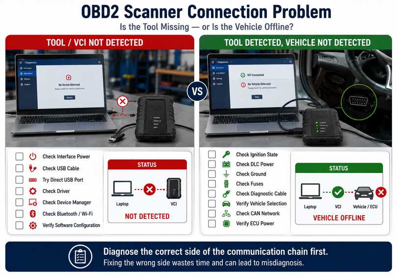
If the diagnostic computer cannot detect the interface, troubleshoot the USB connection, wireless connection, driver installation, interface power, and software configuration. If the interface is detected but the vehicle remains offline, move to the diagnostic connector, ignition state, vehicle power, network, and ECU communication.
Condition A: Scanner/VCI Is Not Detected
Typical signs:
- Interface does not appear in software.
- USB device missing
- Bluetooth or Wi-Fi connection unavailable
- Driver error appears
- Interface status remains offline.
Check:
- Interface power
- USB cable
- USB port
- Driver
- Device Manager
- Bluetooth/Wi-Fi configuration
- Interface firmware requirements
- Diagnostic software configuration
Do not start diagnosing the vehicle CAN bus when the computer cannot even communicate with the diagnostic interface.
Condition B: Scanner Is Detected, but Vehicle Cannot Be Found
Typical signs:
- VCI status is connected
- Software opens normally
- Vehicle identification fails
- ECU scan returns no modules
- Communication DTCs appear
Check:
- Vehicle battery condition
- Ignition status
- Diagnostic connector power and grounds
- Fuses
- Cable/adapter
- Vehicle selection
- CAN/network integrity
- ECU power and ground
- Scanner coverage
This distinction prevents unnecessary software reinstallations.
What Is the Correct Diagnostic Workflow After Reading a Code?
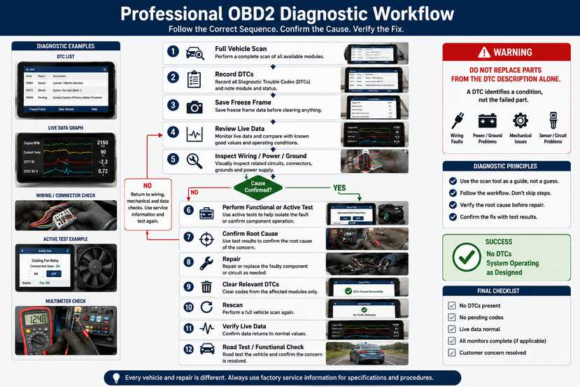
Do not immediately clear a fault code or replace the component named in the description. Record the DTC and freeze-frame information first, reproduce the complaint, compare live data, inspect the relevant circuit, use active tests where appropriate, repair the confirmed fault, and only then clear codes and verify the result.
Step 1 — Perform a Complete Scan
Record:
- DTC number
- DTC status
- ECU containing the code
- Related codes in other modules
Communication or voltage faults across several controllers can reveal a system-level problem rather than several simultaneous component failures.
Step 2 — Save Freeze-Frame Data
Freeze-frame data may show operating conditions when the fault was detected.
Useful values can include:
- Engine RPM
- Load
- Coolant temperature
- Vehicle speed
- Fuel-system status
Do this before clearing codes.
Step 3 — Review Live Data
Compare the suspected sensor or actuator against:
- Related sensors
- Known operating behavior
- Manufacturer specifications
Avoid declaring a component failed from one abnormal number without checking power, ground, wiring, and operating conditions.
Step 4 — Perform Physical and Electrical Checks
Inspect:
- Harness
- Connectors
- Power
- Ground
- Fuses
- Vacuum/pressure lines where applicable
- Mechanical condition
A scan tool cannot detect every physical fault directly.
Step 5 — Use Active Tests Where Appropriate
A bidirectional test can help separate:
command problem → circuit problem → actuator problem
But only perform tests when the vehicle is safely positioned, and the commanded component cannot create a hazard.
Step 6 — Repair the Confirmed Cause
Repair the verified fault rather than replacing parts based only on the DTC title.
Step 7 — Clear Codes and Rescan
After repair:
- Clear relevant DTCs.
- Cycle the ignition as required.
- Restart the vehicle.
- Perform the appropriate operating cycle.
- Rescan all relevant modules.
- Review live data again.
Normal Results vs Abnormal Results
Diagnostic data is useful only when it is interpreted in context. A “normal” result means the communication path and measured behavior match expected operating conditions or manufacturer specifications; an “abnormal” result should trigger additional testing before replacing a component.
| Test | Normal result | Abnormal result |
| Scanner detection | Interface recognized | Interface absent/offline |
| Vehicle identification | Correct VIN/model detected | No VIN or incorrect vehicle |
| Module scan | Expected ECUs communicate | One/multiple ECUs offline |
| DTC rescan after repair | Fault stays cleared | DTC immediately returns |
| Live data | Plausible and responsive | Fixed, implausible or inconsistent |
| Active test | Component responds correctly | No response/unexpected response |
Confirm exact electrical values and sensor ranges in the relevant manufacturer’s service information.
Common OBDII Scanner Mistakes
Most scanner-related mistakes come from expecting a diagnostic tool to make the diagnosis automatically. A scanner provides evidence from vehicle controllers; the technician must still interpret that evidence, test the electrical or mechanical system, and verify that the requested function is actually supported.
Mistake 1 — “The Code Says Sensor, So Replace the Sensor”
Correction: Check the circuit and operating conditions first.
Mistake 2 — Clearing Codes Before Recording Them
Correction: Save the complete scan and freeze frame before clearing anything.
Mistake 3 — Assuming “OBD2 Compatible” Means Full-System Diagnosis
Correction: Verify individual ECU coverage.
Mistake 4 — Confusing Coding with Programming
Correction: Verify exactly which operation the software supports.
Mistake 5 — Choosing by Model Count
A claim such as “supports thousands of cars” says little about whether one critical function works on your vehicle.
Correction: Verify the exact:
Vehicle + ECU + Function
Mistake 6 — Ignoring Protocol Requirements
A scanner with conventional CAN support may not provide every function required on newer architectures using CAN FD or DoIP.
Mistake 7 — Treating Heavy-Duty Equipment Like a Passenger Car
A 16-pin connector does not automatically make a commercial vehicle compatible with a passenger-car scanner.
When Should You Stop Diagnosis or Programming?
Stop when the procedure creates an electrical, mechanical, security, or high-voltage risk that exceeds the equipment, information, or training available. Reading DTCs is relatively low risk; programming an ECU, operating a hydraulic actuator, or servicing a high-voltage vehicle can have significantly greater consequences.
Stop and obtain appropriate service information or professional assistance if:
- You cannot maintain the ECU programming voltage.
- You cannot verify the correct calibration file.
- Communication drops repeatedly during programming.
- A control module is not securely identified.
- An active test could cause unexpected vehicle or machine movement.
- High-voltage hybrid/EV systems must be opened or isolated.
- Immobilizer/security functions require authorized credentials.
- Airbag/SRS procedures require circuit manipulation.
- Manufacturer programming instructions are unavailable.
Do not experiment with ECU firmware.
Post-Repair Verification Checklist
A repair is not complete simply because the warning lamp turns off. Verification should confirm that the original DTC does not return, the relevant live data behaves correctly, the repaired system completes its required functional test, and no new faults were introduced elsewhere in the vehicle.
After repair:
Rescan the affected ECU.
Perform a complete vehicle scan where appropriate.
Confirm the original DTC does not return.
Check pending DTCs.
Compare repaired-system live data.
Perform an appropriate functional or active test.
Complete required calibration/relearn.
Confirm warning indicators operate correctly.
Verify readiness status when emissions diagnosis is involved.
Road-test or operate the vehicle when safe and required.
Perform a final scan.
Remember that clearing emissions-related DTCs can reset readiness information. A recently cleared vehicle may therefore show incomplete readiness monitors even if no current code is present.
How to Select an OBD2 Diagnostic Tool for Your Workshop
The right OBD2 diagnostic tool supports the vehicles, ECUs, and procedures your workshop handles. A technician who only needs emissions-code diagnosis has very different requirements from a workshop performing active tests, coding, ADAS work, ECU programming or heavy-duty diagnostics.
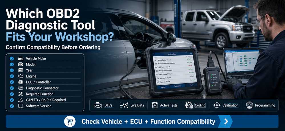
Before buying any scanner, send or verify:
Vehicle Make → Model → Year → Engine → ECU/Controller → Connector → Required Function
For newer vehicles, also check:
- CAN FD requirement
- DoIP requirement
- Security Gateway access
- Software subscription
- Programming capability
- VCI compatibility
For heavy-duty or construction-equipment work, additionally confirm:
- J1939 or manufacturer-specific protocol
- Correct machine cable
- OEM diagnostic software
- Interface driver
- Operating-system compatibility
Which Scanner Level Fits You?
Vehicle owner / occasional DIY diagnosis
Choose a reliable code reader with DTCs, freeze frame, readiness and useful live data.
Choose a reliable code reader with DTCs, freeze frame, readiness and useful live data.
Advanced DIY / independent general repair
Look for multi-system scanning, live-data graphing, service functions and suitable active tests.
Look for multi-system scanning, live-data graphing, service functions and suitable active tests.
Professional automotive workshop
Prioritize broad ECU coverage, bidirectional control, advanced protocols, topology where useful, software support and clear function-level compatibility.
Prioritize broad ECU coverage, bidirectional control, advanced protocols, topology where useful, software support and clear function-level compatibility.
ECU programming workshop
Verify the required OEM software, J2534 or manufacturer interface capability, CAN FD/DoIP requirements, battery support and authorization before choosing equipment.
Verify the required OEM software, J2534 or manufacturer interface capability, CAN FD/DoIP requirements, battery support and authorization before choosing equipment.
Truck / agricultural / construction shop
Use a heavy-duty or OEM-specific diagnostic solution where required rather than assuming a passenger-car OBDII scanner will provide appropriate controller access.
Use a heavy-duty or OEM-specific diagnostic solution where required rather than assuming a passenger-car OBDII scanner will provide appropriate controller access.
Technicians who need more than basic emissions-code reading can browse professional automotive diagnostic tools at OBD2Tool and compare options according to vehicle, ECU, required function, CAN FD/DoIP support and software compatibility.
FAQ
Is an OBDII scanner worth buying?
Yes, when the scanner matches the diagnostic work you actually perform. A basic tool is useful for reading standardized emissions-related DTCs and live data, while professional users may require multi-module diagnostics, active testing, coding or programming support.
Do all OBDII scanners work with every car?
No. Standardized OBD-II functions are much more consistent than manufacturer-specific ECU functions. You must confirm ABS, SRS, BCM, coding, active tests, and programming for the exact make, model, year, ECU, and software version.
Can an OBDII scanner tell me exactly which part is bad?
Usually not. A DTC identifies a fault condition the ECU detected. Wiring, power, ground, connectors, mechanical faults, or another component can produce the same code. Confirm the root cause before replacing parts.
Can an OBDII scanner reset the Check Engine Light?
A compatible scanner can usually clear emissions-related DTCs, but it clears codes only after recording diagnostic information and repairing the cause. Clearing codes can also reset emissions readiness monitors.
Is a full-system scanner the same as an ECU programmer?
No. Full-system diagnosis means accessing multiple vehicle modules. ECU programming means writing software or calibration data to a controller and may require entirely different hardware, software, authorization, and power-support procedures.
What is bidirectional control?
Bidirectional control allows diagnostic software to send supported commands to an ECU, such as commanding a relay or actuator. Availability is vehicle- and ECU-specific.
Why does my scanner connect to the computer but not the vehicle?
If the computer detects the interface, troubleshoot the vehicle side next: diagnostic connector power and ground, ignition state, cable, fuses, network communication, ECU power, and scanner coverage.
Can a passenger-car OBDII scanner diagnose heavy-duty trucks?
Not necessarily. Commercial vehicles can require HD-OBD, SAE J1939, dedicated connectors, manufacturer interfaces, and OEM diagnostic software. Check compatibility for the specific truck and engine.
Do I need CAN FD or DoIP?
Only when the target vehicle and required diagnostic function use those communication technologies. Confirm the vehicle architecture and scanner/VCI capability before purchasing.
Final OBDII Scanner Buying Checklist
Before ordering, confirm:
Vehicle manufacturer
Model
Year
Engine
ECU/controller
Region
Diagnostic connector
Required protocol
Required systems
DTC reading
Live data
Active tests
Coding
Calibration
Programming
CAN FD / DoIP if required
Security access requirements
Software/update policy
Operating-system requirements
Conclusion
Select an OBDII scanner as a diagnostic system, not a list of advertised features. Start with the vehicle, identify the controller, define the function, confirm the communication technology, and only then choose the scanner and software.
For basic Check Engine Light work, a generic OBD-II reader may be enough. For professional diagnostics, coding, active testing, ECU programming or heavy-duty equipment, the required tool can be substantially different.
Before purchasing an OBD2 diagnostic tool from OBD2Tool, confirm your make, model, year, engine, ECU/controller, connector, and required function so the scanner’s capabilities match the job.