*For 1.8L 4-cylinder engines (C-Class, E-Class, SLK-Class)*
Critical Pre-Repair Step
⚠️ Always back up full ECU data using compatible programmers (CG FC200, Xhorse Multi Prog, OBDSTAR DC706) before disassembly.
Common Issue 1: Ignition Fault & Intermittent Misfire
Symptoms: Random cylinder misfires, ignition errors.
Root Cause: Capacitor leakage causing board corrosion/short circuits.
Repair Procedure:
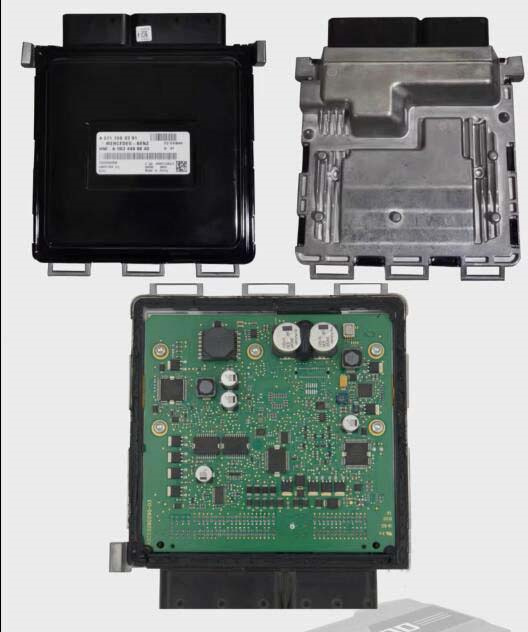
- Disassemble ECU .
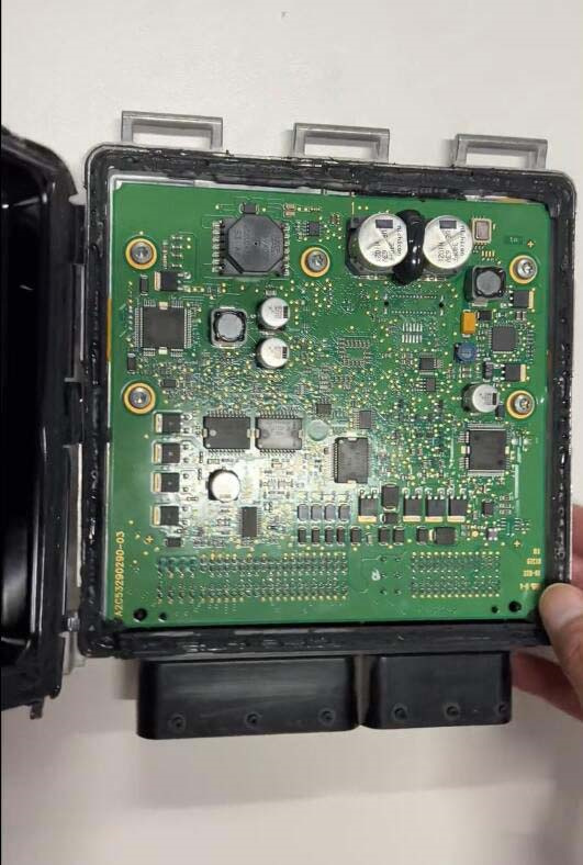
- Replace leaking capacitors.
- Clean corrosion from affected resistors and PCB using isopropyl alcohol.
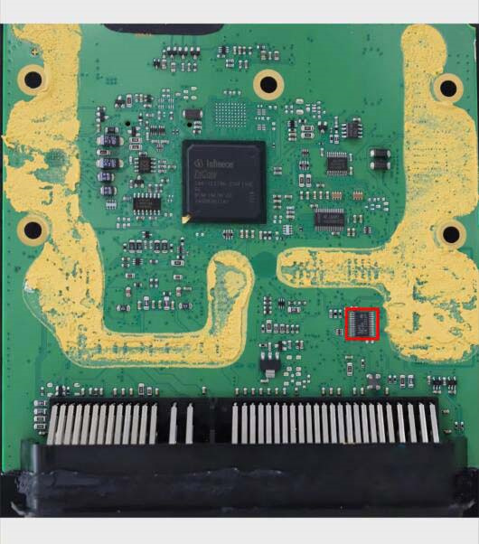
- Inspect ignition control chip (Backside of board)
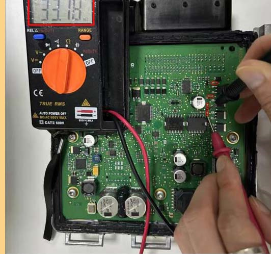
- Desolder, clean pins, test with multimeter.
- Replace if damaged; reflow if functional.
- Test shutdown resistors:
- Verify 33 kΩ resistance on all four.
- Replace out-of-spec resistors.
Common Issue 2: Throttle Body Fault
Symptoms: Sudden loss of acceleration, engine/ESP warning lights.
Diagnostic Codes: Throttle body or pedal sensor faults (P0120-P022X series).
Solutions:
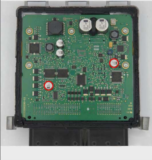
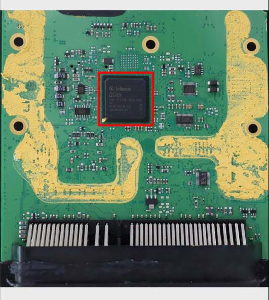
- Reflow BGA chip.
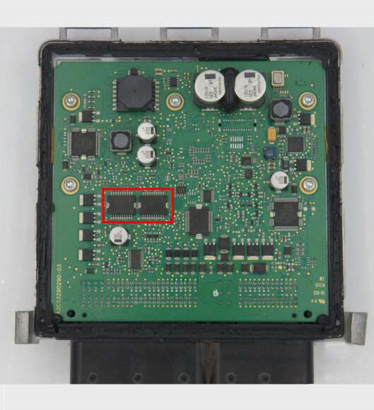
- Address throttle drive chips:
- Step 1: Resolder both chips.
- Step 2: If fault persists, replace chips (P/N: 0 281 002 635).
- Step 1: Resolder both chips.
Common Issue 3: Crankshaft Position Sensor Fault
Symptoms: P0335-P0339 codes, erratic RPM readings, no-start.
Repair Steps:
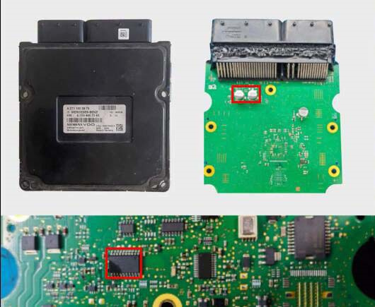
- Capacitor replacement :
- Remove leaking capacitors.
- Neutralize electrolyte residue.
- Chip inspection:
- Replace damaged processing chip caused by short circuits.
- Replace damaged processing chip caused by short circuits.
Post-Repair Validation
- Reassemble ECU securely.
- Restore backed-up data.
- Clear fault codes and test:
- Verify stable idle.
- Check throttle response.
- Confirm sensor readings live data.
Key Notes:
- Capacitor leaks are the primary failure trigger in 80% of cases.
- Always wear ESD protection during handling.
- Use leaded solder for BGA rework to prevent cold joints.
Image References:
- Image 1: ECU disassembly
- Image 2: Faulty capacitor location
- Image 3: Ignition control chip
- Image 4: Shutdown resistors
- Image 5: BGA chip position
- Image 6: Throttle drive chips
- Image 7: Sensor circuit capacitors
- Image 8: Signal processing chip
Why This Structure Works:
- Problem-Solution Focus: Directly links symptoms to actionable fixes.
- Prioritizes Safety: Emphasizes critical data backup first.
- Technical Precision: Uses standard diagnostic codes (P-codes) and part numbers.
- Visual Workflow: Image references integrated at relevant repair stages.
- Validation Steps: Adds post-repair checks missing in the original.
This format meets technician needs for quick scanning while maintaining repair rigor.