Introduction
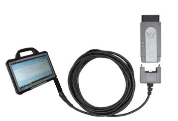
In case you encounter errors or problems when using the new VAS 6154 VCI, here are some possible fixes that you can use or try out yourself before you need to contact support. This provision is intended to help you use the VAS 6154 quickly and efficiently.
This document refers to one of the three available diagnostic modes that the VCI offers:
• USB
Note: the following information refers to the standard VAS 6154 configuration:
Requirements:
o Standard IP addresses for the VCI
o Activated DHCP server in both USB and access-point mode
1. USB connection
1.1 Requirements:
1. USB cap must be in place on the VCI
2. VCI must be connected to the tester via USB
For further information please refer to the operating instructions of the VAS
6154.
1.2 Locating faults:
If you are losing connections with the VAS 6154 in USB mode please try the following suggestions, which may resolve the problem:
1. Visual check of the VCI’s LED display
2. Does the tester have an existing network connection to the VCI?
3. Ping the VAS 6154 (ping must be permitted by the IT system)
4. Use the ACTIA PDU-API tester
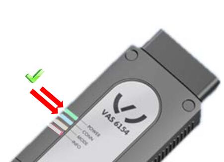
1. Visual check of the VCI’s LED display
Desired state:
Successful connection status:
When you have successfully connected the VCI to the tester via USB, both the green and blue LEDs will be lit:
• green – VCI is active
• blue – connection to tester has been set up
Note: the blue LED will flicker while data is being transferred.
Error situation:
Blue LED flashes (once per second):
If the blue LED is flashing this indicates that it is waiting for a connection to the tester. If the flashing does not quite soon become a steady light, this indicates that it is not possible to establish a connection. In this case, check:
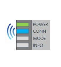
(1) that the VAS 6154 is connected via the original USB cable
(2) whether the USB cap’s serial number is listed as defective (see the document: VAS 6154-4 USB-module serialnumbers.xlsx)
(3) in Windows’ Device Manager for a virtual network interface (to check the network, see item 2: “Does the tester have an existing network connection to the VCI?”). If the network interface does not appear, check the driver installation and reinstall ODIS Service.
Green LED is flashing:
If the green LED is flashing rather than steadily lit, then there is a system error.
Use Windows Explorer to navigate to the location XS_D_PDU_API -> manual,
open the User Manual in your national language and check the reason for the
flashing green LED. Follow the recommended steps. If this does not help, or if the
document does not list your particular problem, please contact ACTIA Support.
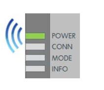
Only the green LED is lit:
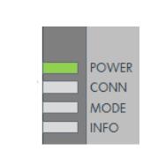
The VCI is starting up. Please wait a few seconds
All the LEDs on the VCI are off:
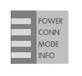
The VCI has no power supply or is in power saving mode (for further information, see the Annex: “Power Saving Mode”). Power saving mode is standardly initiated after 15 minutes. You can reactivate the VCI by performing an ignition reset, or by restarting the device by unplugging it from the USB and then reconnecting it again. This setting can be disabled in the configuration.
2. Does the tester have an existing network connection to the VCI?
To check the network connection from the tester to the VCI, open the Device Manager on your tester and check whether the VCI is listed as a network adapter “VAS6154 (USB)”:
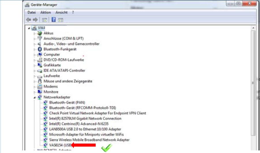
If no network adapter is listed, check:
(1) whether the USB cap’s serial number is listed as defective.
(2) check the driver installation and reinstall ODIS service.
3. Ping the VAS 6154 (must be enabled by the IT system)
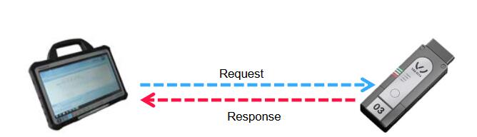
You can test the connection between two network devices by issuing a ping.
To issue a ping the tester sends a small network packet to the receiving station (in this case the VAS 6154). If the other party responds to the ping, this guarantees that the configuration is correct and that a connection is open.
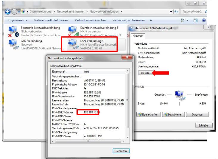
To issue a ping you will need the VCI’s IP address. In the standard configuration, the VAS 6154 is assigned the IP address 192.168.13.69 for USB mode.
Note: The VCI’s configuration interface can be used to change this default configuration.
If you do not know the IP address, go to the following locations on your tester: Control Panel -> Network and Internet -> Network Connection, then click on your specific VCI, and you will find its IP address under Details… .
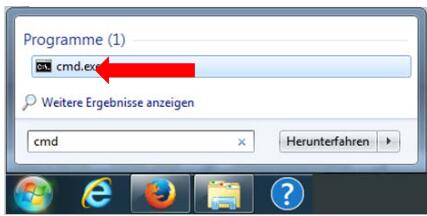
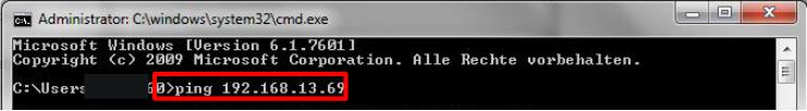
Then, go to your Windows Start menu, open the program cmd.exe and enter the following text “ping 192.168.13.69” (if your VCI’s IP address differs from this default value please modify the ping command accordingly).
The test is successful if the other party sends an appropriate response, as you will see below:
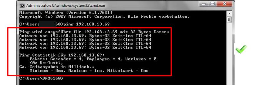
If the test is not successful, ask your network administrator to check the network configurations (IP addresses+subnet masks) of the tester and the VCI.
4. Use the ACTIA PDU -API tester
To perform this test, open the ACTIA PDU-API tester. This is located on the following drive: C:\ODIS-DIAG- MODULES\PDUAPI\ VEN-IME\IME_D-PDU_API_ Tester.exe.
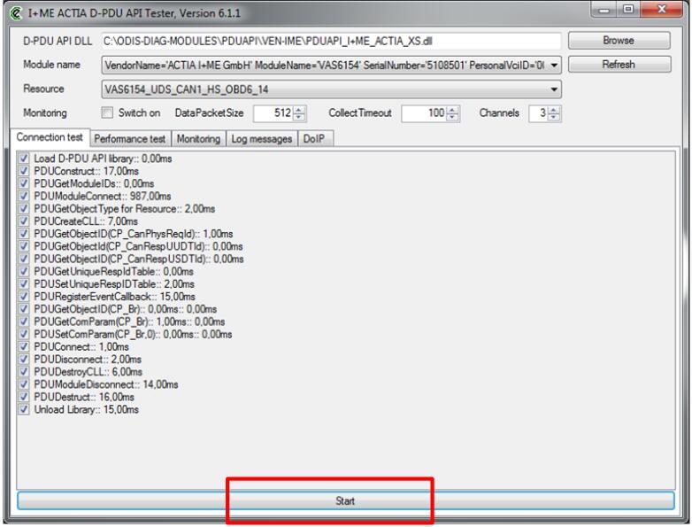
Here you can perform a test by clicking on “Start” . If you have a number of VAS 6154 devices connected to the tester, make sure you have selected the correct VCI.
If, at the end of the test, each of the items is shown with a “tick” after it, then the test was successful:
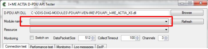
VCI was not found in the tester application:
Step 1: Restart the VAS 6154
If the VCI is not found by the tester application, temporarily disconnect the VCI’s power supply. To do this, unplug both the USB and the OBD connections. All the LEDs should go out. Then try again to set up a connection (if necessary, restart the tester).
Step 2: Set up the file VAS6154-Static-Devices.ini
If the VCI is still not found, this may be because a firewall is preventing you from searching for the VCI in the network. In this case you will need to configure the tester in such a way that the VAS 6154 can be reached via the network host name.
To do this you will need to modify the configuration file “VAS6154-Static-Devices.ini” on the tester.
When ODIS has been installed, you will find the configuration file at the following location:
C:\ProgramData\I+ME Actia GmbH\VAS6154 Driver\VAS6154-Static-Devices.ini

Use a text editor to open this file and insert a new section:
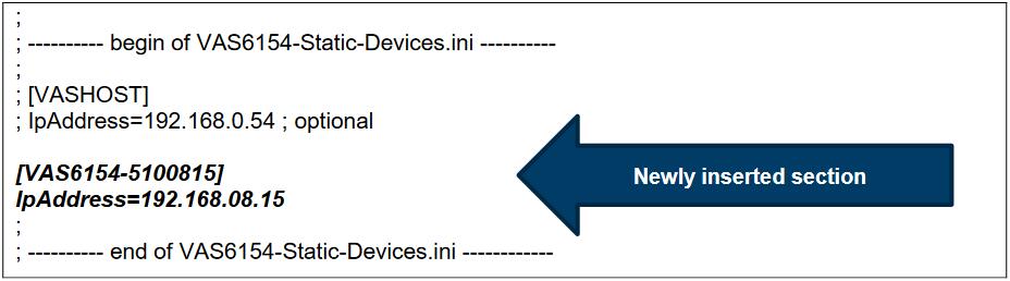
If the device’s IP address is fixed, and known, then you have the option of entering it in the file. This enables the VAS 6154 to be located much more quickly.
NOTE: The extra lines you add to the file may not begin with a semicolon!
Restart the tester and try to set up a connection again.
If all the above tests were successful but you still cannot find the VAS 6154 in ODIS Service, or cannot link to it, use the LogHelper utility (see the document: Loghelper4.0.pdf) to gather together the extended logs and send in a support request.
As one final check, restart the tester and see whether it is then possible to set up a connection to the
VAS 6154.
Power save mode

Power Management:
• only visible in administration mode
• Power-saving settings
The VAS 6154 has a two-stage shutoff:
Shutoff stage 1: Power save mode
If there is no communication with the diagnostic device or the vehicle for a (default) period of 15 minutes (diagnostic end), then the VAS 6154 will switch into its initial shutoff stage. When communication is reestablished, the VAS 6154 will switch back to normal operation.
Shutoff stage 2: Automatic shutdown
If there is no communication with the diagnostic device or the vehicle for a (default) period of 30 minutes (diagnostic end), then the device will switch right off. You can reactivate the VAS 6154 by switching the ignition off and back on (terminal 15). This will restart the VAS 6154. The
VAS 6154 will also be restarted if it is disconnected from the power supply and then reconnected. The process of starting up the VAS 6154 can then take up to one minute.
Note: If the VAS 6154 is operated with the USB module, it does not switch right off.
If you are logged on as an Administrator you can access information in the web interface or configure the timers governing the shutoff stage of the diagnostic interface:
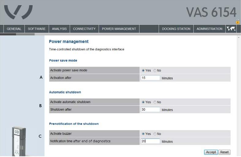
In the web interface you can change the settings governing the two shutoff stages and the buzzer.