John-Deere30294039-40456059-6068-Engines Connecting Rod Bushing Replacement(TAPERED PIN-END CONROD)
Using JDG738 Connecting Rod Bushing Service Set, proceed as follows.
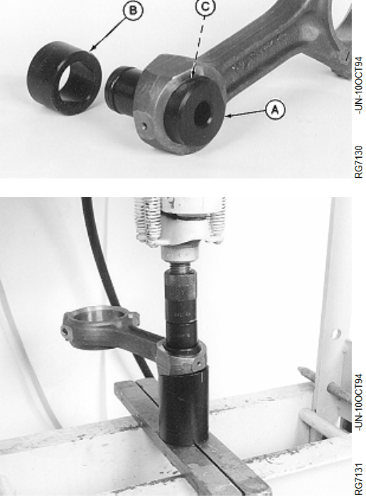
1. Slide driver JDG738-1 (A) into one side of rod bushing (C). Turn driver until taper on driver flange
matches up with taper on bushing.
2. Install receiver cup JDG738-3 onto opposite side of rod bushing.
NOTE: Stud in cup keeps rod properly located on the cup. Use JDG738-2 pilot ring (B) as a hollow spacer when pressing bushing out of rod.
3. Using hydraulic press, push bushing out of rod until driver and bushing fall into receiver cup
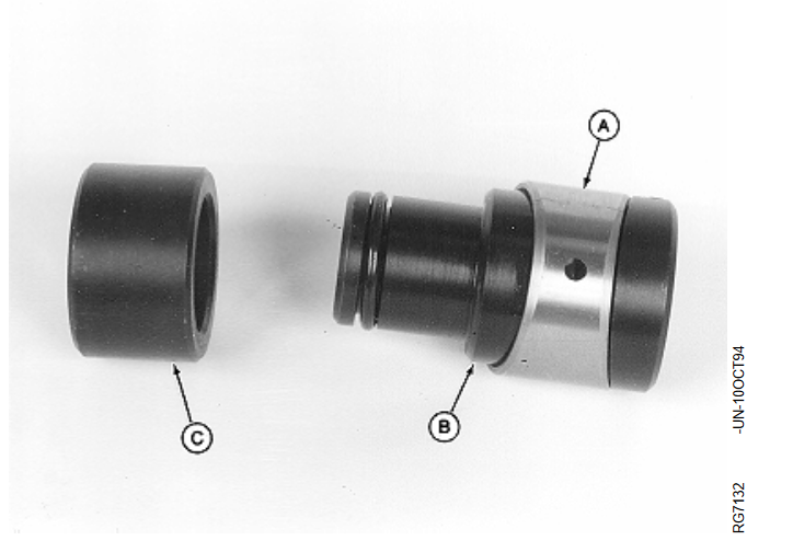
4. Slide bushing (A) onto JDG738-1 driver (B) and install JDG738-2 pilot ring (C) onto O-ring end of driver.
5. Apply TY6333 grease* to:
Outside diameter of bushing
Outside diameter of pilot ring
Inside diameter of rod pin bore
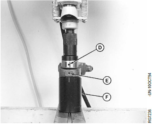
6. Insert driver into rod pin bore so pilot ring pilots in rod bore and bushing taper aligns with taper on driver flange. Align oil hole in bushing (D) with oil hole in end
of rod (E).
7. Install JDG738-3 receiver cup (F) onto opposite side of rod so taper on rod aligns with taper on receiver cup.
8. Press bushing into rod until edge of bushing is flush machined surface on connecting rod face.
IMPORTANT: Oil holes MUST be aligned. If holes are not aligned, remove and discard bushing then re-install a NEW bushing.
DO NOT attempt to reuse a bushing.
9. Have the new bushing reamed by a specialized workshop to obtain an oil clearance of 0.020 to 0.056
mm (0.0008 to 0.002 in.) with piston pin.